


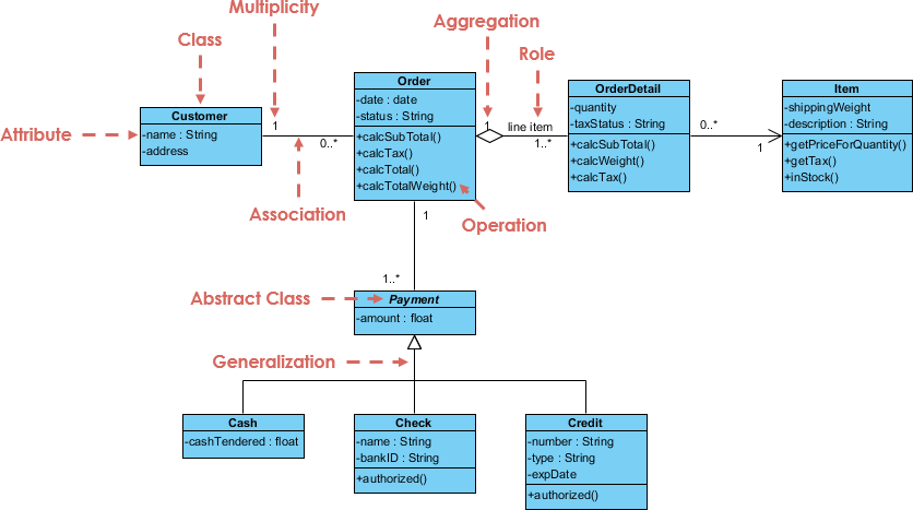
In the realm of software engineering, visual modeling serves as the blueprint for building complex systems. The Class Diagram presented here illustrates a robust architecture for an Order System, a common component in e-commerce and inventory management platforms. This diagram is not merely a static picture; it represents a dynamic structure of data and behavior that developers use to write code. By breaking down the components of this diagram, we can understand how software architects organize logic into manageable units.
Core Components of the Model
The diagram is built upon several distinct classes, each serving a specific purpose within the system’s ecosystem. A Class in UML (Unified Modeling Language) is a template that defines the attributes (data) and operations (methods) of a specific entity.
- Customer: This class represents the user interacting with the system. It holds identifying information like name and address. The negative sign (
-) preceding these attributes indicates private visibility, meaning they are encapsulated and cannot be accessed directly from outside the class. - Order: This is the central transactional class. It manages the state of a purchase, including the creation date, status, and total amount. It contains operations like calcSubTotal() and calcTotal(), denoted by the plus sign (
+) for public visibility. - OrderDetail: This class acts as a bridge between an Order and its contents. It captures specific details about the items being purchased, such as quantity and taxStatus.
- Item: This represents the physical or digital goods available for sale, containing properties like shippingWeight and description.
Mapping Relationships and Logic
Perhaps the most critical part of a class diagram is how these classes interact. The diagram uses specific lines and symbols to define the “grammar” of the software’s structure.
- Association: The line connecting Customer and Order represents an association. The notation
1near Customer and0..*near Order indicates a Multiplicity constraint: one Customer can place zero or many Orders. - Aggregation: The relationship between Order and Item is an aggregation (represented by the hollow diamond). This implies a “whole-part” relationship where the parts (Items) can exist independently of the whole (Order). If an order is cancelled, the Item still exists in the database.
- Generalization: The arrows pointing from Cash, Check, and Credit up to Payment represent inheritance. This is a “is-a” relationship. A Cash payment is a type of Payment. This allows the system to treat all payment methods polymorphically, using the shared Payment class as a base.
The Agile Workflow: From Idea to Code
Modern software development has evolved beyond manual drag-and-drop diagramming. The text provided outlines a sophisticated pipeline that integrates AI, version control, and automated code generation. This approach, often called “Diagram as Code,” ensures that the design remains synchronized with the actual software implementation.
1. Ideation and AI Chatbot
The process begins with the VP AI Chatbot. Instead of starting with a blank canvas, a Product Owner or Architect can type natural language requirements directly into the chat. The AI analyzes these prompts and instantly constructs a baseline UML class diagram. This allows for rapid iteration. If the team realizes they need to add a “status” attribute to the Staff class, they can simply ask the chatbot to update the model, bypassing the need to manually redraw shapes.
2. Architecture-as-Code with VPasCode
Once the design is finalized, it is exported into the VPasCode platform. This converts the visual model into a text-based syntax (similar to PlantUML). This is a crucial step for modern DevOps. By saving the model as a plain text file (e.g., .puml or .vpascode), the architecture becomes a part of the application’s Git repository.
- Version Control: Developers can track changes to the architecture alongside changes to the source code.
- Peer Review: Design changes are merged via standard Pull Requests, ensuring that the system structure is reviewed by the team before it is deployed.
3. Engineering and Deployment Handoff
The final stage involves the Visual Paradigm Desktop or browser environment. Developers pull the approved script into their environment, where it renders back into a standard-compliant visual diagram. The system supports bidirectional synchronization, meaning changes made in the code can update the diagram, and vice versa. Furthermore, the platform offers Forward Engineering, where the finalized class diagram is used to instantly generate boilerplate code skeletons in languages like Java, Python, or C#, significantly accelerating the actual development phase.
Conclusion
By combining the precision of UML with the agility of AI and the discipline of Git, teams can build systems that are both well-architected and easy to maintain. The Order System diagram serves as a perfect example of how abstract concepts like Aggregation and Generalization translate into concrete, robust software structures.
Related posts:
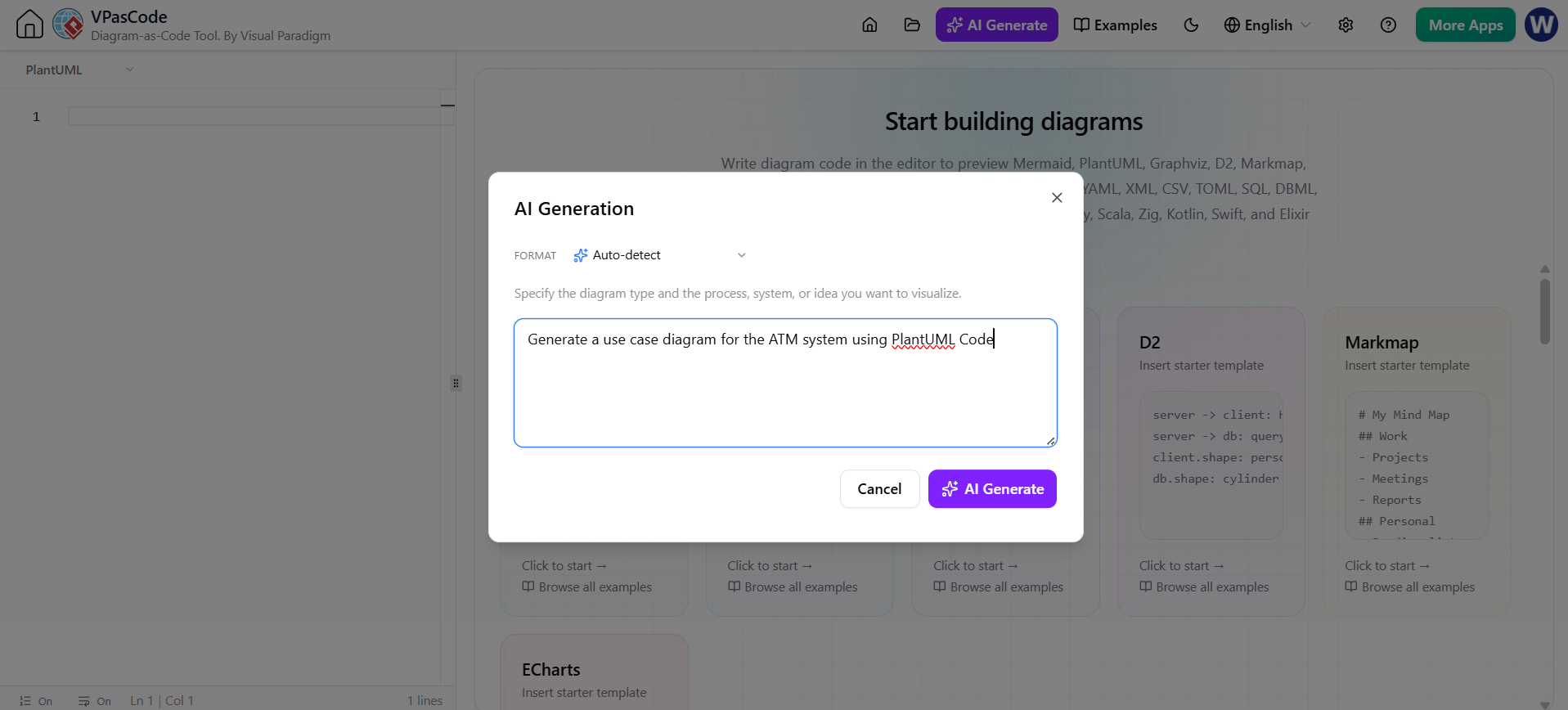 Revolutionizing System Modeling: The Power of Instant AI Diagram Generation
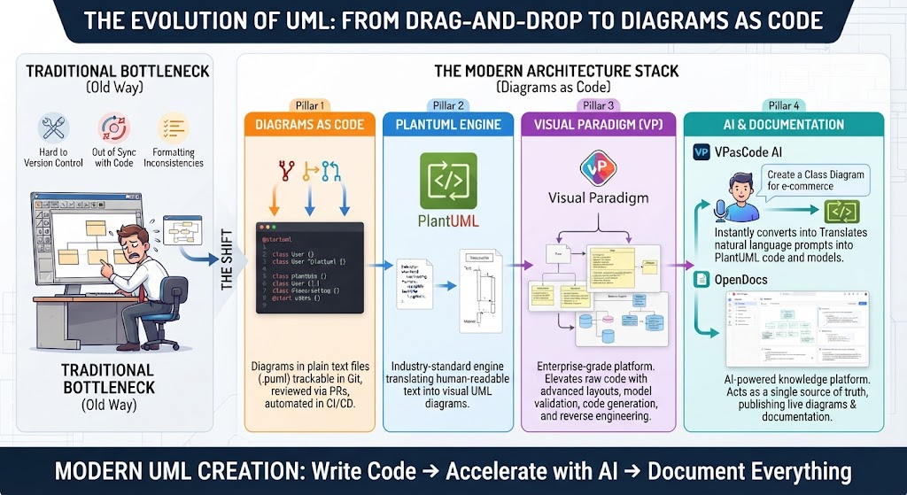 The Evolution of UML: Mastering the Modern Architecture Stack from Drag-and-Drop to Diagrams as Code
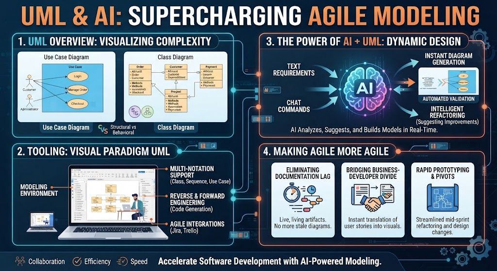 UML & AI: Supercharging Agile Modeling for Modern Software Architecture
 Mastering System Design: A Deep Dive into Visual Paradigm Community Edition