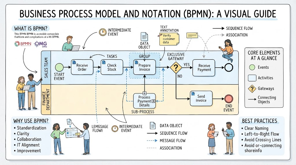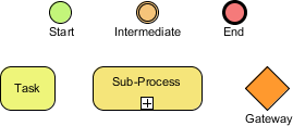
Welcome to this tutorial session on the fundamental components of business process modeling. When we look at a complex workflow, whether it’s an automated software routine or a manual approval procedure, we are essentially looking at a sequence of steps. In the world of BPMN (Business Process Model and Notation), these steps are defined by Flow Elements. These elements dictate the behavior and flow of a process, determining where it starts, what work gets done, where decisions are made, and how it concludes.
Just as a builder needs bricks, mortar, and beams to construct a house, a business analyst needs these specific shapes to construct a valid process model. Let’s break down the three primary categories of Flow Elements visible in standard modeling diagrams.
1. Events: The Triggers and Terminators
Events are the things that happen during a process. They are represented by circles and act as the boundaries of activities. In Visual Paradigm, these are often the first elements you place on a diagram to define the scope of your workflow.
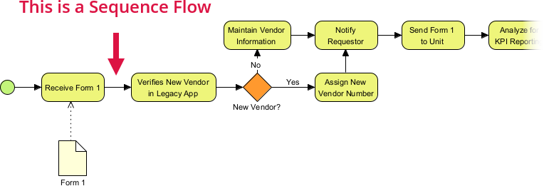
- Start Event (Green Circle): This is the genesis of your process. It signifies that the process is triggered. For example, a “Customer places order” event initiates the fulfillment workflow. In Visual Paradigm, selecting this element allows you to define specific triggers, such as a message arrival or a timer start.
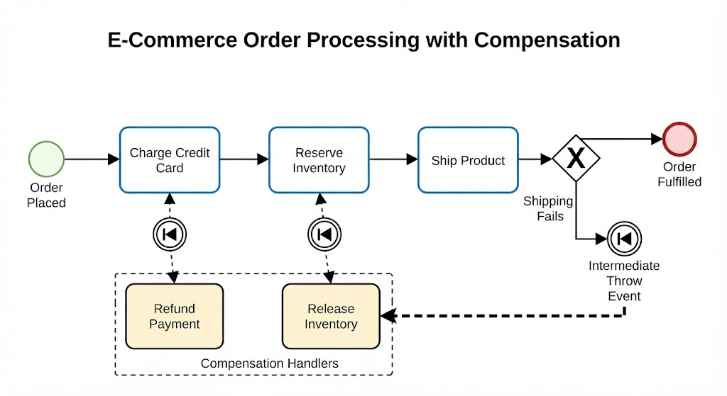
- Intermediate Event (Orange Ring): These events occur between the start and end of a process. They represent something that happens during the flow, such as a delay, a message being received, or an error occurring. They essentially pause the flow or add a condition to it. Visual Paradigm makes it easy to attach these to sequence flows to show exactly when a pause or a catch occurs.
- End Event (Red Circle): This marks the successful (or unsuccessful) termination of a process. It indicates that no further activities are expected. It is the “checkered flag” of your business process.
2. Activities: The Work Being Performed
Once the process is triggered by an event, the actual work begins. These are the rectangular shapes with rounded corners that represent the “doing” part of the model.
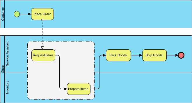
- Task: This is the most basic unit of work. It represents an activity that has no sub-structure visible in the current view. It could be a single action like “Send Email” or “Approve Invoice.” In Visual Paradigm, tasks are highly configurable; you can link them to external code, define service tasks, or assign specific roles to users within your organization.
- Sub-Process: Sometimes, a single task is too complex to be described in one step. A Sub-Process allows you to group multiple tasks together into a single, collapsed unit. Notice the small plus sign + in the bottom corner of the yellow rectangle in our diagram. This indicates that if you expand it, you will reveal a detailed internal process. Visual Paradigm excels here by allowing you to nest models, enabling you to create high-level management dashboards while keeping detailed operational logic in separate, expandable layers.
3. Gateways: The Decision Points
A process rarely flows in a straight line from start to finish. It often involves choices, parallel work, and synchronization. This is where the diamond shape comes into play.
- Gateway (Orange Diamond): This element represents a decision point or a control flow junction. It dictates how the process splits or merges. For instance, a gateway might ask, “Is the order value over $100?” If yes, route to Manager Approval; if no, route to Standard Shipping. In Visual Paradigm, you can easily configure these gateways to be Exclusive (XOR), Inclusive (OR), or Parallel (AND), ensuring your logic accurately reflects real-world business rules.
Applying Flow Elements in Visual Paradigm
Understanding the theory is only half the battle; the real power lies in implementation. Visual Paradigm provides a comprehensive environment to bring these abstract concepts to life.
When you open the BPMN editor in Visual Paradigm, you are presented with a rich palette containing all the elements we discussed. The interface is designed to be intuitive. You can simply drag and drop a Start Event, connect it to a Task, and route it through a Gateway to an End Event. The tool automatically handles the underlying XML structure, ensuring that your diagrams are not just pretty pictures, but valid, executable models.
Furthermore, Visual Paradigm supports the refinement of these elements. If you start with a simple Task and realize it needs more detail, you can transform it into a Sub-Process with a single click. This capability allows for iterative modeling—starting with a high-level overview and progressively drilling down into the nitty-gritty details without losing the context of the overall process.
By mastering these Flow Elements, you gain the ability to communicate complex business logic clearly, efficiently, and without ambiguity. Whether you are designing a simple approval chain or a multi-million dollar enterprise resource planning workflow, these elements remain the universal language of process.