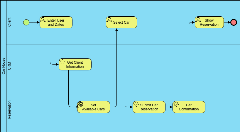
In the world of software engineering and business analysis, visualizing how a system works is just as important as writing the code itself. This article serves as a comprehensive tutorial on interpreting a Business Process Diagram (BPD), specifically focusing on a “Car Rental Process.” We will break down the architecture, explain the flow of data between different actors, and explore the key concepts of BPMN (Business Process Model and Notation) using this example.
Understanding the Architecture: The Swimlanes
The most striking feature of this diagram is its structure. It is organized into horizontal sections known as Swimlanes. These lanes represent different participants or systems responsible for specific tasks. By separating these responsibilities, we can instantly see who is doing what.
In this specific diagram, we see three distinct swimlanes:
- Client: This top lane represents the end-user (the person renting the car). Any task with a human icon in this lane requires user input.
- Car House CRM: The middle lane represents the Customer Relationship Management system. This is likely the administrative interface used by staff.
- Reservation: The bottom lane represents the core booking engine or database system that manages inventory and finalizes bookings.
Step-by-Step Process Walkthrough
Let us trace the flow of this process from the Start Event (the green circle) to the End Event (the red circle). This linear path illustrates the “Happy Path”—the ideal scenario where the user successfully rents a car.
1. Initiation and Data Entry
The process begins in the Client lane. The user performs the first task: Enter User and Dates. This is a manual task indicated by the human icon. Once the user inputs their details and desired rental dates, the flow passes down to the next system.
2. System Processing and Verification
The process moves into the Car House CRM lane. The system executes Get Client Information. Notice the gear icon here; this typically signifies an automated system task rather than a human action. The CRM fetches the user’s profile to verify eligibility or retrieve loyalty status.
3. Inventory Management
Next, the flow moves to the Reservation lane. The system performs Set Available Cars. This task likely queries the database to filter cars based on the dates and client preferences entered earlier. It prepares the inventory list for the user.
4. Selection and Submission
Crucially, the flow moves back up to the Client lane. The user is now presented with the results and performs the task Select Car. This is a critical decision point where the user chooses a specific vehicle. Once selected, the process flows back down to the Reservation lane.
Here, the system executes Submit Car Reservation (an automated task). The booking is finalized in the database. Finally, the system performs Get Confirmation, generating a receipt or booking ID.
5. Completion
The process returns to the Client one last time. The user views the Show Reservation screen. Upon reviewing the details, the process hits the red end circle, signifying the successful conclusion of the workflow.
Key BPMN Concepts Explained
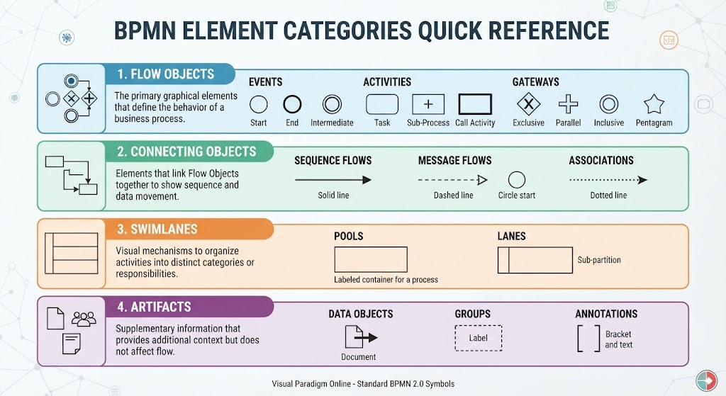
To truly master this diagram, you must understand the symbols used. Here are the technical concepts illustrated in this Visual Paradigm Online model:
- Start and End Events: The green circle represents the trigger that starts the process. The red circle represents the successful termination of the process.
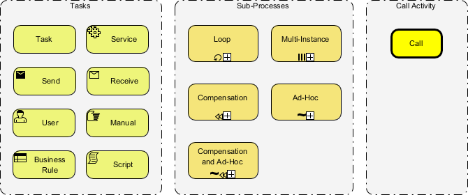
- Tasks (Rounded Rectangles): These yellow boxes represent the work being done. They are the fundamental building blocks of the process.
- Manual vs. Automated Tasks: While the diagram uses a general yellow box, the icons next to them provide nuance.
- Human Icon: Indicates a manual task performed by a person (e.g., “Select Car”).
- Gear Icon: Often indicates an automated system task or a service task (e.g., “Get Client Information”).
- Sequence Flows: The black arrows connecting the tasks show the order of execution. They dictate that one task cannot start until the previous one is complete.
Why Use Visual Paradigm Online for BPMN?
Creating complex diagrams like the one above requires a robust tool. Visual Paradigm Online (VP Online) is a powerful, browser-based tool that supports Business Process Diagrams, UML, ERD, and Organization Charts.
Key Benefits for Modeling:
- Intuitive Editor: As seen in this car rental example, the drag-and-drop interface allows you to quickly assign tasks to specific swimlanes without writing code.
- Free Forever: It offers a comprehensive set of features accessible without immediate cost, making it perfect for students and startups.
- Standard Compliance: It adheres to BPMN standards, ensuring that the diagrams you create are universally understood by business analysts and developers.
By mastering these diagrams, you bridge the gap between business requirements and technical implementation, ensuring that software development is always aligned with real-world user needs.