In the realm of software engineering, visualizing how a system interacts with its users is just as critical as writing the code itself. As noted in our context, UML (Unified Modeling Language) is invaluable for software design and system architecture modeling. It bridges the gap between technical requirements and user needs.
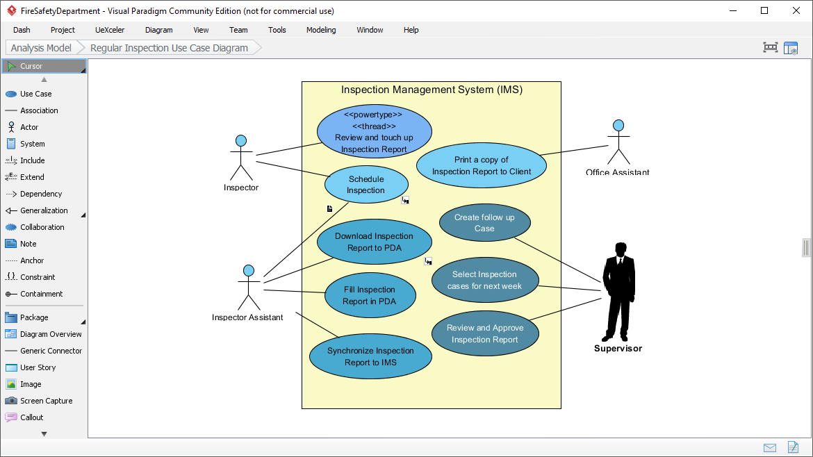
Today, we are analyzing a specific Use Case Diagram created in Visual Paradigm. This diagram models the Inspection Management System (IMS), a system designed to streamline the workflow of field inspections, from scheduling to final approval. By breaking down this diagram, we will learn how to identify actors, map out complex workflows, and interpret technical UML stereotypes.
1. Understanding the System Boundary
The first thing to observe in any UML diagram is the system boundary. In this diagram, the large yellow rectangle represents the Inspection Management System (IMS). Everything inside this box is a function the system performs. Everything outside the box represents an Actor—a role that interacts with the system but is not part of it.
2. Identifying the Actors
Actors are the “who” of our system. They are usually represented by stick figures or silhouettes. In the IMS diagram, we have four distinct roles, each with specific responsibilities:
- Inspector: The primary field worker responsible for conducting inspections. They are the most active user in the system.
- Inspector Assistant: A supporting role, likely assisting the main inspector with data entry or logistics.
- Office Assistant: An administrative role focused on client interaction and document distribution.
- Supervisor: The authority figure responsible for managing the workflow, reviewing reports, and creating follow-up cases.
3. Mapping the Use Cases (The “What”)
Use cases (the blue ovals) represent the specific actions or services the system provides to the actors. We can group these into logical workflows to understand the system’s architecture better.
A. The Field Workflow (Mobile Operations)
The diagram highlights a sophisticated mobile capability, indicated by references to a PDA (Personal Digital Assistant). This suggests the system supports offline data collection.
- Download Inspection Report to PDA: The inspector retrieves data to the field device.
- Fill Inspection Report in PDA: The actual data entry happens on the mobile device.
- Synchronize Inspection Report to IMS: Once back in range, the data is uploaded to the central server.
B. Administrative & Scheduling
These functions ensure the inspection process is organized and timely.
- Schedule Inspection: The system allows for the booking of future inspection slots.
- Print a copy of Inspection Report to Client: Handling the final delivery of results to the stakeholder.
C. Management & Approval
The Supervisor uses the system to oversee quality and plan future work.
- Select Inspection cases for next week: A planning feature for resource allocation.
- Create follow up Case: If an inspection reveals issues, a new case can be generated immediately.
- Review and Approve Inspection Report: The final validation step before a report is considered official.
4. Advanced UML Concepts: Stereotypes
Notice the top-left oval in the diagram: <<powertype>> <<thread>> Review and touch up Inspection Report. This is a great example of how UML can be extended using stereotypes (text inside guillemets) to add technical depth to a model.
- <<thread>>: In software architecture, a thread is a sequence of execution. Marking this use case as a thread suggests that “Reviewing and touching up” might be a background process or a distinct execution flow that allows the inspector to perform other tasks while the report is being processed, or perhaps it runs as a daemon process to ensure data integrity.
- <<powertype>>: In UML, a powertype is a type that can be specialized. In the context of a use case, this might indicate that this specific action is a “meta-action” or a specialized version of a standard review process, perhaps allowing for different levels of review depth.
Conclusion
By modeling the Inspection Management System this way, developers gain a clear roadmap. They know they need to build a mobile synchronization feature, a reporting engine for the supervisor, and a scheduling module for the office. This diagram serves as the contract between the stakeholders and the engineering team, ensuring everyone agrees on how the system behaves before a single line of code is written.