Business Process Model and Notation (BPMN) is the global standard for visualizing business processes. Developed and maintained by the Object Management Group (OMG), BPMN provides a consistent, intuitive, and executable way to model workflows across organizations. It is not merely a diagramming tool; it is a complete modeling language for process design, analysis, automation, and optimization.
This tutorial breaks down the core architectural components of BPMN diagrams, explaining how these graphical symbols bridge the gap between business stakeholders and technical teams. By understanding the syntax of BPMN, you can create Business Process Diagrams (BPDs) that are clear to executives yet precise enough for system architects and developers.
The Core Elements of BPMN
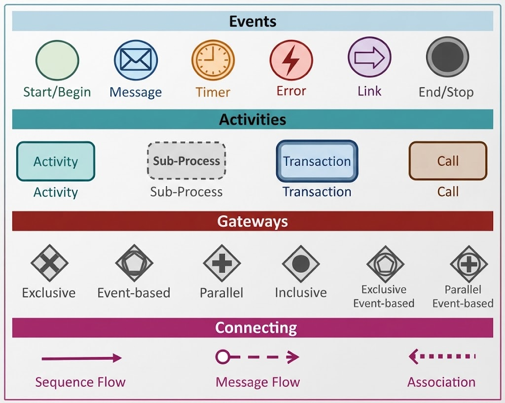
A BPMN diagram is constructed using four primary categories of elements: Events, Activities, Gateways, and Connecting Objects. Each shape carries specific semantic meaning regarding the state of the process.
1. Events: The “Something Happens” Moments
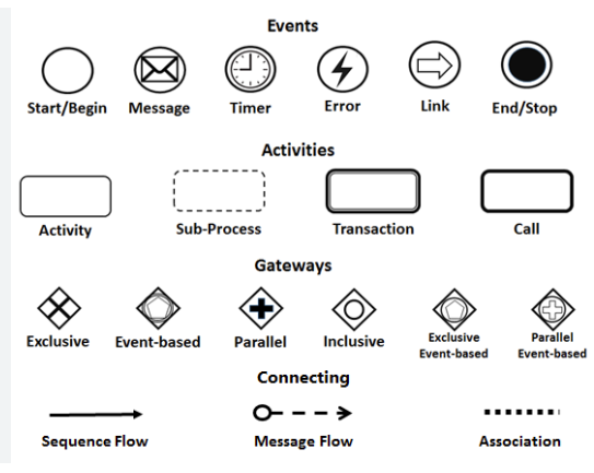
In BPMN, events are represented by circles. They signify something that happens during the course of a process—something that triggers an activity or marks its conclusion. The thickness of the circle line often indicates the nature of the event.
- Start / Begin Event: A thin-lined circle indicating the initiation of a process. It is the entry point where the process starts.
- End / Stop Event: A thick-lined circle representing the termination of a process. This marks the successful or failed conclusion of a workflow.
- Intermediate Events: Circles with a single thin line that occur between a start and end. These include:
- Message: Represents the sending or receiving of a message (e.g., an email or API call).
- Timer: Represents a time-based trigger (e.g., “Wait 2 days” or “Start at 9:00 AM”).
- Error: Represents an error condition that interrupts the flow.
- Link: Used to link a section of the diagram to another part of the same diagram.
2. Activities: The Work Being Done
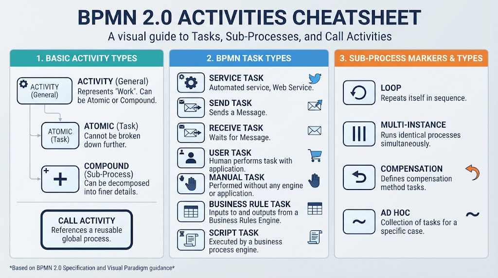
Activities represent the actual work performed in a process. They are depicted using rounded rectangles. Unlike events, activities have duration and effort associated with them.
- Task (Activity): The smallest unit of work. It is an atomic action that cannot be broken down further within the context of the current diagram.
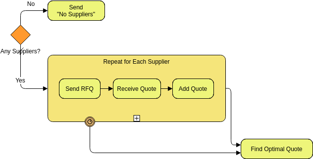
- Sub-Process: A group of activities that can be expanded into a separate, more detailed diagram. This allows for abstraction, keeping high-level diagrams clean while allowing deep dives into complexity.
- Transaction: A special type of sub-process where the activities are guaranteed to be executed exactly once (atomicity). If any part fails, the entire transaction rolls back.
- Call Activity: A reference to a reusable global task or sub-process defined elsewhere.
3. Gateways: The Decision Points
Gateways are represented by diamonds. They do not represent work; instead, they control the divergence and convergence of the sequence flow. They determine the path the process takes next.
- Exclusive Gateway (XOR): The most common gateway. It allows only one path to be taken out of several options (e.g., “If order is valid, go to shipping; if not, go to rejection”).
- Parallel Gateway (AND): Represents a synchronization point. It splits one flow into multiple simultaneous flows (e.g., send email AND update database) and waits for all to complete before continuing.
- Inclusive Gateway: Allows one or more paths to be taken based on conditions (e.g., “If insured, send policy; if not insured, send quote”).
- Event-Based Gateway: Waits for a specific event to occur (like a timer or message) to determine the next path.
Connecting the Dots: Flow and Interaction
To make the diagram dynamic, these elements must be connected. BPMN defines specific line styles to indicate the nature of the relationship between objects.
Sequence Flow
Represented by a solid line with an arrow, this defines the order of activities. It shows the path from one activity to the next within a single process instance.
Message Flow
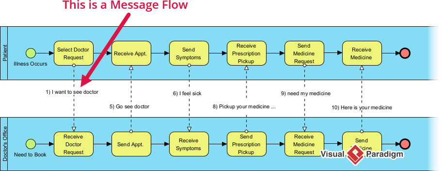
Represented by a dashed line with an open arrow, this indicates communication between different participants (e.g., between a Customer and a Bank). It is crucial for showing interactions across boundaries.
Association
Represented by a dotted line, this connects an artifact (like a text annotation or data object) to a specific activity, providing context or documentation without affecting the flow logic.
Why BPMN 2.0 Matters
While earlier versions of process modeling were static, BPMN 2.0 introduced executable semantics. This means that diagrams are not just pictures; they can be directly deployed in process engines (e.g., Camunda, Activiti, Flowable). The clear definition of gateways, events, and flows allows technical teams to automate the workflow exactly as the business stakeholders designed it.
Whether you are modeling private internal processes, public collaborations between organizations, or choreographies for distributed interactions, BPMN provides the universal language to visualize the complex machinery of modern business.