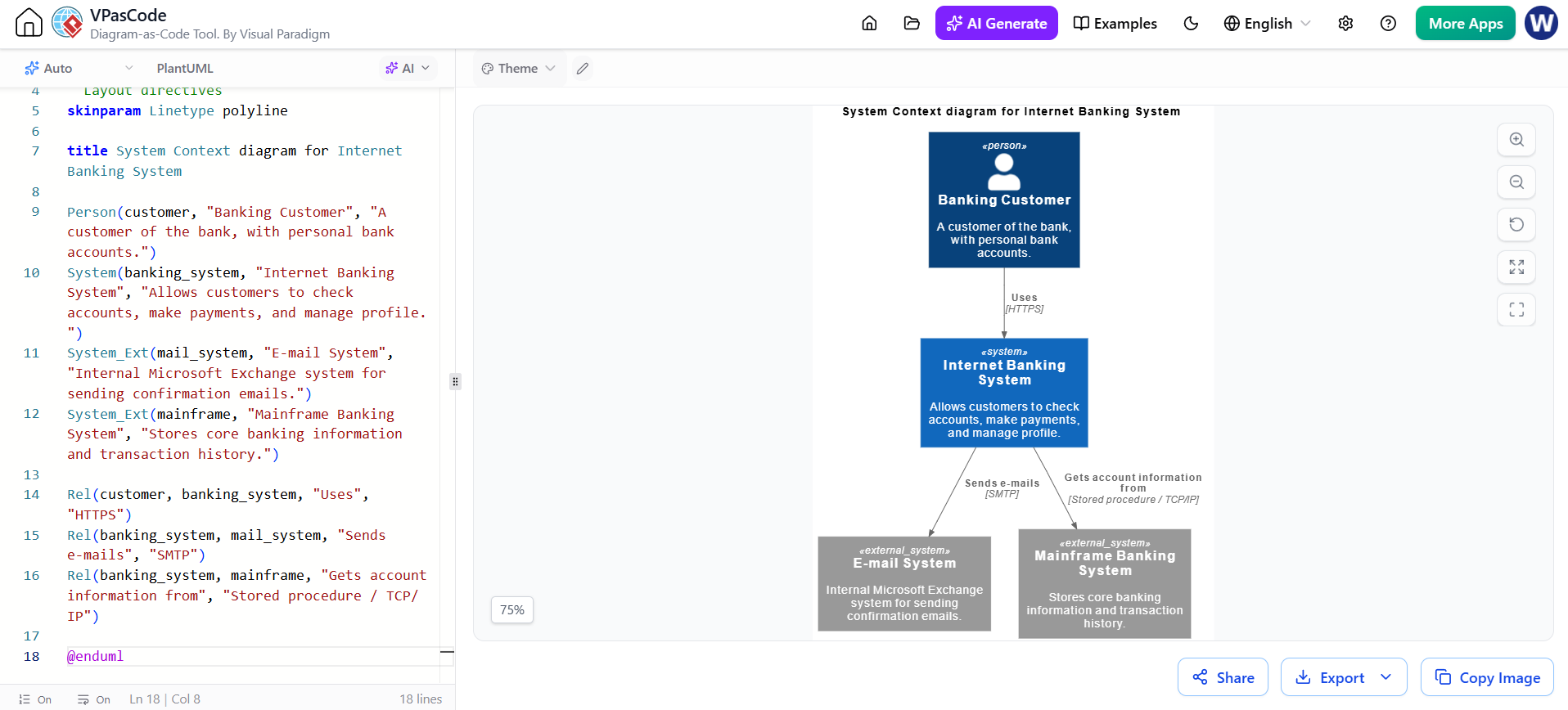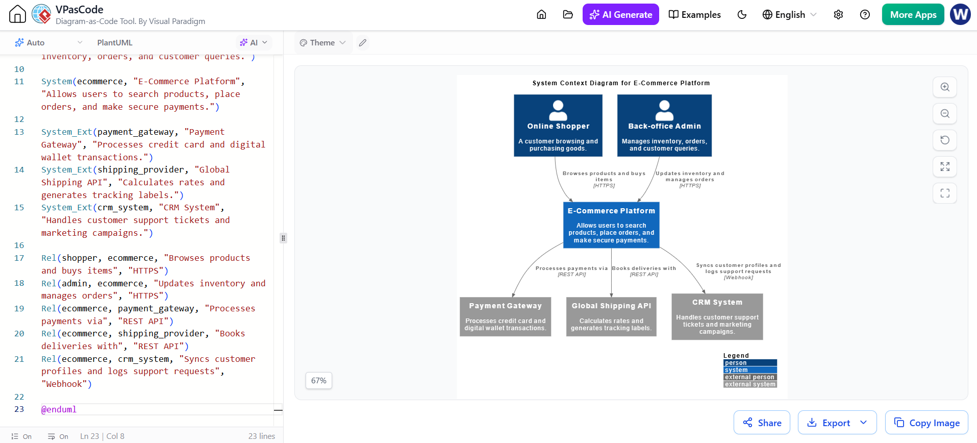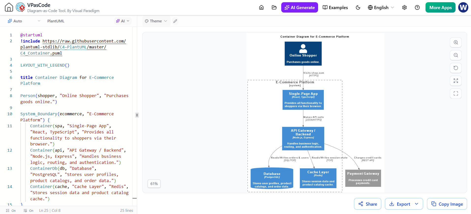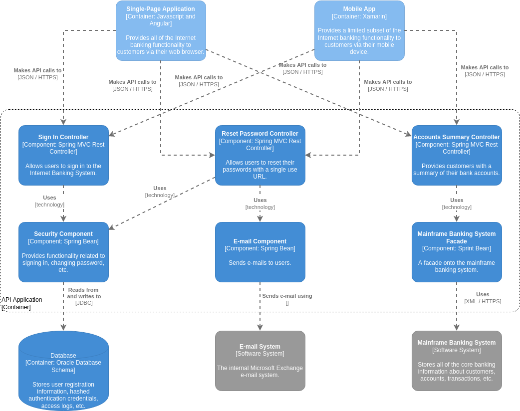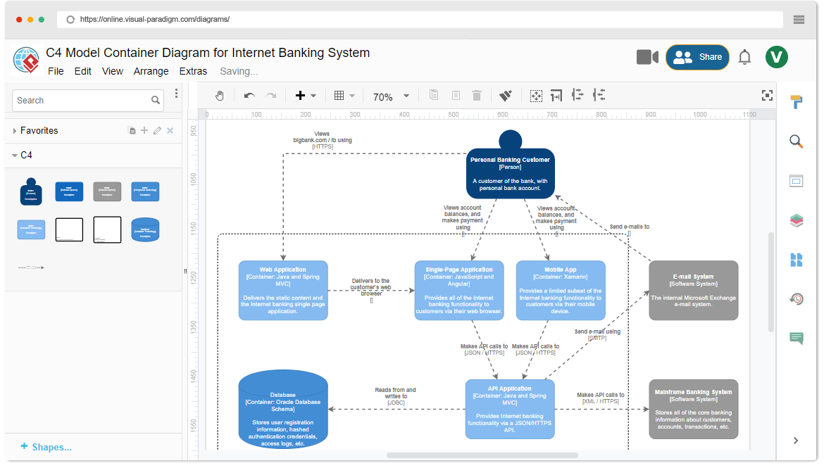
In the complex world of software architecture, communicating the “big picture” is often more difficult than writing the code itself. This is where the C4 model shines. The image provided above is a classic example of a Container Diagram within the C4 hierarchy. It visualizes the high-level software architecture of an Internet Banking System, breaking it down into distinct software containers and their interactions.
In this tutorial, we will walk through this diagram step-by-step. We will deconstruct the layers, explain the specific technologies mentioned, and analyze how this architectural view helps developers and stakeholders understand the system’s flow.
Understanding the C4 Hierarchy
Before diving into the diagram, it is essential to understand where this view sits in the C4 model. The C4 model is a set of hierarchical abstractions designed to help architects visualize software systems at different levels of detail. It consists of four levels:
- System Context: The highest level, showing the system and its users.
- Container: The level shown in the image. It zooms in to show the high-level building blocks (containers) that make up the system.
- Component: A deeper dive into the individual components within a container.
- Code: The lowest level, dealing with class diagrams and source code.
The diagram we are analyzing is the Container Diagram. It answers the question: “What are the major runtime processes and data stores, and how do they interact?”
Anatomy of the Internet Banking Diagram
The diagram is structured to show the flow of data from the user, through various applications, to the backend systems. Let’s break it down by element type.
1. The User (Person)
At the top center, you will see a blue circle labeled “Personal Banking Customer”. In C4 notation, this represents a Person. This is the actor initiating the request. The text below it defines their role: “A customer of the bank, with personal bank account.”
2. The Containers (Software Systems)
The blue rounded rectangles in the middle and bottom rows represent Containers. A container is a high-level building block of a software system, such as a web application, a mobile application, a microservice, or a database.
In this banking system, we see three distinct entry points for the user:
- Web Application: Labeled with the container type
[Container: Java and Spring MVC]. This is a traditional server-side rendered application. - Single-Page Application (SPA): Labeled with
[Container: JavaScript and Angular]. This represents a modern frontend application that runs in the browser. - Mobile App: Labeled with
[Container: Xamarin]. This indicates a cross-platform mobile application.
Key Architectural Insight: Notice the arrow from the “Web Application” pointing to the “Single-Page Application” with the label “Delivers to the customer’s web browser”. This indicates a specific architectural pattern where the Java/Spring MVC app acts as a delivery mechanism (perhaps serving the initial HTML/JS bundle) for the Angular SPA.
3. The Backend Infrastructure
Below the user-facing applications, we find the core logic and data storage:
- API Application: The central hub labeled
[Container: Java and Spring MVC]. This container likely acts as a microservice or API gateway, providing the backend logic for the frontend applications. - Database: The bottom-left blue shape labeled
[Container: Oracle Database Schema]. This stores the user data. The text notes it stores “user registration information, hashed authentication credentials, access logs, etc.”
4. External Systems
On the right side of the diagram, there are grey rectangles. In C4, these represent External Systems—systems that are outside the immediate control of your team but are necessary for the system to function.
- E-mail System: Labeled
[Software System]. This is the internal Microsoft Exchange system used for sending notifications. - Mainframe Banking System: Labeled
[Software System]. This is the legacy system that stores the “core banking information about customers, accounts, transactions, etc.”
Tracing the Data Flow (Relationships)
The arrows in the diagram represent the flow of data. The labels on the arrows explain the protocol or technology used. Let’s trace a typical transaction:
- Authentication: The Personal Banking Customer interacts with the Web Application via HTTPS to view their account.
- Application Logic: The Web Application delivers the Single-Page Application to the browser. Alternatively, the Mobile App interacts directly with the API Application.
- API Communication: Both the Single-Page Application and the Mobile App “Make API calls to” the API Application using JSON over HTTPS.
- Data Persistence: The API Application “Reads from and writes to” the Oracle Database using JDBC (Java Database Connectivity).
- Legacy Integration: The API Application communicates with the Mainframe Banking System using XML over HTTPS to retrieve core account data.
- Notifications: The Mobile App and the API Application can “Send e-mail using SMTP” to the E-mail System.
Utilizing Visual Paradigm for C4 Modeling
The screenshot provided is a snapshot of Visual Paradigm’s online C4 Model tool. This tool is designed to make the creation of such diagrams accessible and efficient. Here is why this tool is particularly effective for the diagram shown:
- Pre-built C4 Shapes: On the left sidebar, you can see the “Favorites” panel containing the specific shapes required for the C4 model (Person, Container, External System). This ensures consistency in notation without needing to draw boxes manually.
- Technology Tagging: The tool allows you to easily annotate containers with specific technology stacks (e.g.,
Java and Spring MVC,Xamarin), which is clearly visible in the diagram’s text boxes. - Notation Independence: As mentioned in the C4 principles, this tool allows teams to adapt the model. Here, the team chose a specific color scheme (Blue for internal containers, Grey for external systems) to visually distinguish between owned assets and third-party integrations.
- Collaboration: The “Share” button at the top right indicates that this diagram can be shared with stakeholders, facilitating the “Effective Communication” benefit mentioned in the C4 model principles.
Conclusion
This Container Diagram is a perfect example of how the C4 model simplifies complex architecture. By breaking the Internet Banking System into distinct containers and clearly labeling the data flow protocols (HTTPS, JDBC, SMTP), it provides a clear roadmap for developers and a high-level overview for stakeholders. Whether you are using Visual Paradigm or a whiteboard, the principles of hierarchical abstraction remain the same: start with the system, zoom into the containers, and focus on the relationships that make the software work.