In the world of software architecture and business analysis, clarity is king. One of the most powerful tools for achieving this clarity is BPMN (Business Process Model and Notation). Think of BPMN as a universal language that allows business stakeholders and technical developers to communicate process flows without ambiguity. Just as an architect uses blueprints to visualize a building, a business analyst uses BPMN diagrams to visualize complex workflows.
This tutorial will deconstruct the architecture of BPMN, breaking down the four core elements illustrated in the standard notation and guiding you through the practical steps of building your first professional-grade diagram.
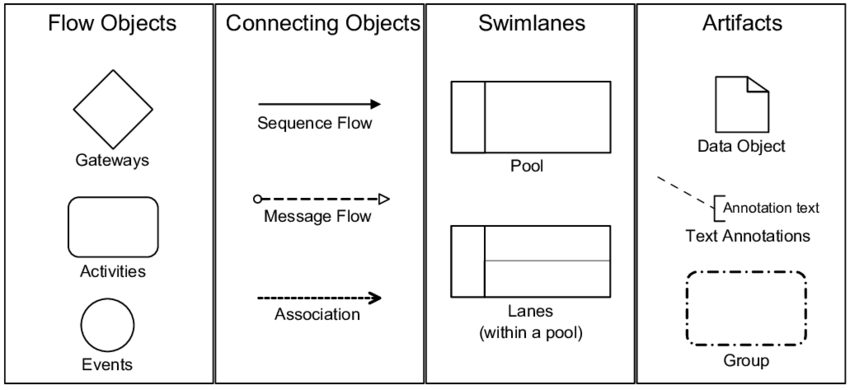
The Four Core Elements of BPMN
At the heart of every BPMN diagram are four primary categories of elements. Understanding these building blocks is essential for constructing a logical and accurate process map.
1. Flow Objects: The Core Building Blocks
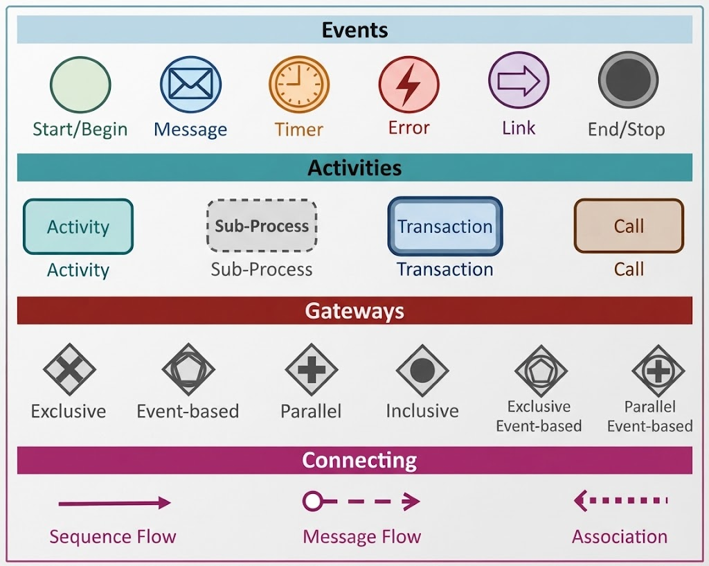
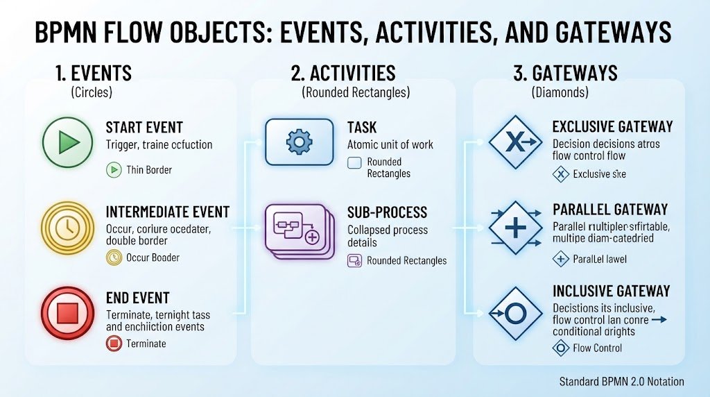
Flow objects are the active ingredients of your diagram. They define what actually happens within the process. As shown in the visual guide, these are represented by distinct shapes:
- Events (Circles): Events are things that happen. They trigger or interrupt the flow.
- Start Event: A plain circle representing the initiation of the process.
- Intermediate Event: A circle with a double border, occurring in the middle of a process (e.g., receiving an email or a timer expiring).
- End Event: A thick-bordered circle, signifying the termination or completion of the process.
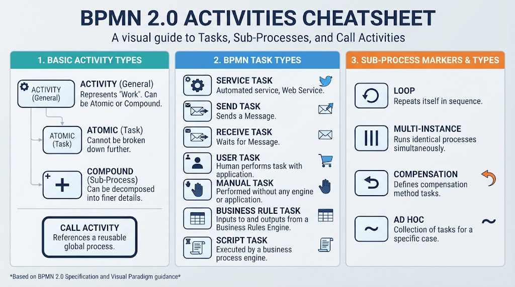
- Activities (Rounded Rectangles): These represent work being done.
- Task: An atomic unit of work that cannot be broken down further (e.g., “Review Contract”).
- Sub-Process: A group of related tasks collapsed into a single element to manage complexity.
- Gateways (Diamonds): These are decision points that control the direction of the flow.
- Exclusive Gateway: A binary decision (e.g., Yes/No) where only one path is taken.
- Parallel Gateway: Used to split flow into multiple simultaneous paths.
- Inclusive Gateway: One or more paths are taken based on evaluated conditions.
2. Connecting Objects: How Elements Interact
Flow objects need to be linked to show the sequence of events. These connectors define the “glue” of the process:
- Sequence Flow (Solid Line with Arrowhead): The most common connector. It shows the order in which activities are executed.
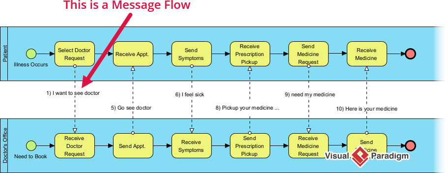
- Message Flow (Dashed Line with Arrowhead): Crucial for interactions between different participants. It represents the exchange of information (like an email or a document) between pools or lanes.
- Association (Dashed Line): Links artifacts, such as data objects or annotations, to specific flow objects without implying a sequence.
3. Swimlanes: Who Does What?
Process diagrams can become chaotic if it isn’t clear who is responsible for a task. Swimlanes organize activities by role or responsibility:
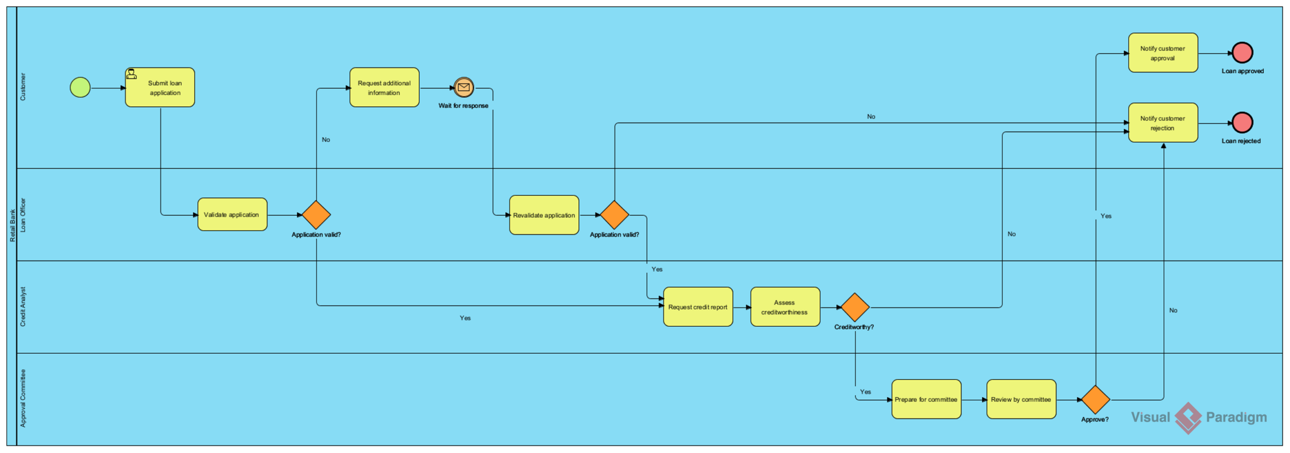
- Pools: Represent high-level participants in the process (e.g., “Customer,” “Bank,” “Supplier”).
- Lanes: Subdivisions within a pool. If a Pool represents a “Department,” Lanes might represent specific roles like “Manager,” “Clerk,” or “Auditor.”
4. Artifacts: Additional Information
Not everything in a diagram needs to be a step in the flow. Artifacts provide context:
- Data Objects: Icons representing the data used or produced (e.g., a “Purchase Order”).
- Text Annotations: Notes or comments used to clarify complex elements.
- Groups: A visual grouping of elements (dashed box) that does not affect the process flow logic.
Step-by-Step Guide to Building BPMN Diagrams
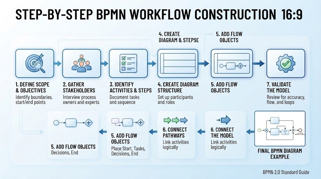
Now that you understand the vocabulary, let’s put it into practice. Follow this structured approach to model a business process effectively.
- Define the Scope and Objectives: Before drawing, articulate why you are modeling this process. What are the start and end points? What is the desired outcome?
- Gather Stakeholders: Involve process owners and subject matter experts. Their input ensures the model reflects reality, not just assumptions.
- Identify Activities and Steps: Break the process down into individual tasks. Document what is done, by whom, and in what sequence.
- Create the Diagram Structure: Start by adding pools and lanes. Ensure every process model has at least one pool to define the boundaries of the participants.
- Add Flow Objects: Place your Start Event, followed by Tasks, Gateways, and finally the End Event. Connect them using Sequence Flows.
- Add Decision Points: Insert Gateways wherever a business decision is required. Use descriptive names (e.g., “Application Approved?”) rather than generic labels.
- Validate the Model: Walk through the process from start to finish. Check for logical errors, dead loops, or missed nodes. Use software validation tools if available.
Visualizing the Workflow Construction
Imagine the process of building a BPMN diagram as assembling a modular system. You begin with the foundational structure (Pools and Lanes), then populate it with active components (Flow Objects), and finally connect them with precise pathways (Connectors). This modular approach ensures that even complex business logic remains structured and manageable.
Best Practices and Common Pitfalls
To ensure your diagrams are professional and easy to understand, adhere to these industry standards and avoid common traps.
Best Practices
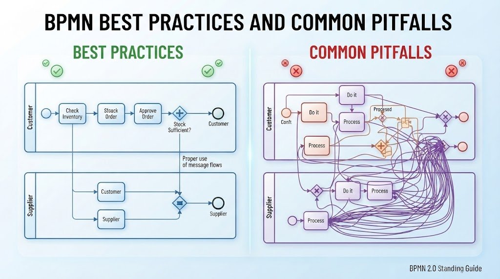
- Consistent Naming: Use Verb + Noun for tasks (e.g., “Review Contract”) and interrogative statements for Gateways (e.g., “Is Start Date > 30 days?”).
- Layout Discipline: Maintain a consistent left-to-right workflow direction. Avoid crossing lines wherever possible to maintain readability.
- Manage Complexity: If a process is too complex, use Sub-Processes to collapse details rather than overloading a single diagram.
Common Pitfalls to Avoid
- Misuse of Symbols: Do not mix event types loosely. For example, avoid using a Task for communication when a Message Event is appropriate. Consistency is key.
- Overcomplicating Diagrams: Cluttered diagrams overwhelm viewers. Simplify by focusing on key activities and using sub-processes for complex sections.
- Neglecting Documentation: Without proper annotations, models become difficult to understand. Always include context for complex elements.
Achieving Clarity Through Structure
The difference between a confusing mess and a professional blueprint often lies in the discipline of layout and the clarity of decision points. A well-structured diagram acts as a visual contract, ensuring that every stakeholder, from the CEO to the developer, sees the exact same path of execution.
Getting Started with Tools
To begin your journey in BPMN, you will need a modeling tool. Recommended tools include:
- Visual Paradigm: A comprehensive tool for BPMN modeling capabilities.
- Camunda: Excellent for developers, offering BPMN cheat sheets and reference materials.
The most effective way to learn is through practice. Choose an existing process in your organization, gather your stakeholders, and start modeling. Remember, effective process modeling is an iterative skill that improves with feedback.