In the complex world of business analysis and system architecture, clarity is king. Business Process Model and Notation (BPMN) serves as the universal flowchart language that bridges the gap between how business people talk and how technical teams build systems. Think of it as a standardized graphical representation designed to map out business processes with precision.
Whether you are a business analyst, project manager, or entrepreneur, understanding the core building blocks of BPMN is essential for identifying bottlenecks, ensuring compliance, and laying the groundwork for digital transformation. This tutorial breaks down the visual language of BPMN, transforming vague workflows into structured, actionable maps.
1. The Foundation: Flow Objects (The Action)
At the heart of every BPMN diagram are the “Flow Objects.” These are the graphical elements that represent the actual work, events, and decisions within a process. They are the actors in your process play.
Events
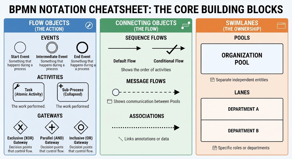
Events are represented by circles and signify “something that happens” during a process. They have no size or direction, acting as the triggers and outcomes of your workflow.
- Start Event: Represented by a thin-bordered circle. This is the trigger that initiates the process (e.g., “Customer submits order form”).
- Intermediate Event: Represented by a circle with a single thin border. This signifies something that happens in the middle of a process, such as a message being received or a timer expiring.
- End Event: Represented by a thick-bordered circle. This defines the ultimate completion of the process (e.g., “Order shipped and invoice paid”).
Activities
Activities represent the work performed. They are typically depicted as rounded rectangles.
- Task (Atomic Activity): The smallest unit of work that can be performed. It is the basic building block of a process (e.g., “Review Application”).
- Sub-Process: A complex task that can be broken down into smaller steps. Visually, this is a rounded rectangle with a small plus sign (+), allowing you to “collapse” details and drill into them separately.
Gateways
Gateways are decision points that control the path of the flow. Represented by diamonds, they determine how the process branches or merges.
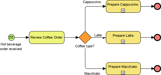
- Exclusive (XOR) Gateway: A diamond with an “X”. This represents a decision where only one path can be taken (e.g., “Approved” vs. “Rejected”).
- Parallel (AND) Gateway: A diamond with a plus sign (+). This indicates that multiple paths must be executed simultaneously.
- Inclusive (OR) Gateway: A diamond with a circle. This allows for multiple paths to be taken, but not necessarily all of them.
2. The Connectors: Connecting Objects (The Flow)
Just as roads connect cities, connecting objects link your flow objects together to show the sequence and relationship between them.
Sequence Flows
These are solid lines with arrows showing the order of activities. They indicate that one task must be completed before the next begins.
- Default Flow: The standard path taken when no specific condition is met.
- Conditional Flow: A path taken only if a specific condition is true (often labeled with a question mark).
Message Flows
Message flows are represented by dashed lines with a hollow circle at the start and a solid arrow at the end. Crucially, these show communication between different organizational pools (e.g., communication between a Client and a Vendor), rather than the sequence of work within a single system.
Associations
These are dotted lines that link text annotations or data objects to flow objects. They provide extra context, policy reminders, or define the data being passed between tasks without altering the flow logic.
3. The Structure: Swimlanes (The Ownership)
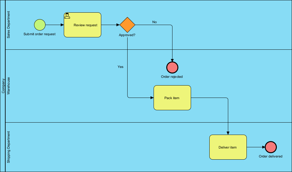
Swimlanes provide the context of “who” is doing the work. They organize the diagram by role, department, or system.
Pools
Pools represent separate independent entities or organizations. If you have a message flow crossing from one pool to another, you are dealing with two different systems or companies.
Lanes
Lanes are sub-partitions within a pool. They represent specific departments, roles, or systems (e.g., “Sales,” “Finance,” or “Accounting”). Keeping tasks within the correct lane is vital for identifying which department owns a specific step in the process.
4. Step-by-Step: Building Your First BPMN Diagram
Now that you understand the vocabulary, here is how you construct a model from scratch, following the standard best practices.
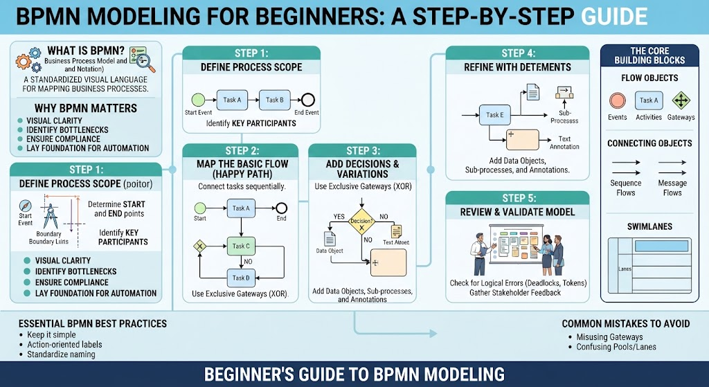
- Define Your Process Scope: Before drawing, define your boundaries. Identify the trigger (Start Event) and the completion criteria (End Event). Keep it simple—limit your initial map to 2 or 3 primary roles to avoid cognitive overload.
- Map the Basic Flow (The Happy Path): Start with the ideal scenario. Place your Start Event on the far left. Connect it via a Sequence Flow to your first Task. Continue adding tasks sequentially until you reach the End Event. Keep lines clean and avoid crossing paths.
- Add Decisions and Variations: Real-world processes aren’t linear. Introduce Gateways to handle exceptions. Use Exclusive Gateways (XOR) for “Yes/No” forks and label your outgoing flows clearly (e.g., “Approved” vs. “Rejected”).
- Refine with Detailed Elements: As the diagram grows, use Sub-Processes to collapse complex tasks. Add Data Objects (document icons) to represent inputs/outputs and use text annotations for context.
- Review and Validate: Check for logic errors. Ensure every token entering a gateway reaches an end event. Avoid infinite loops. Walk through the diagram with stakeholders to spot missing exceptions.
5. Essential Best Practices & Common Mistakes
To ensure your diagrams are professional and actionable, adhere to these guidelines:
Best Practices
- Action-Oriented Labels: Name tasks using a Verb + Noun structure (e.g., “Approve Loan”) rather than vague descriptions.
- Keep It Simple: Stick to core elements (tasks, events, gateways) before experimenting with advanced symbols.
- Standardize Conventions: Maintain consistent layout flows (typically left-to-right) and uniform lane sizing.
Common Mistakes to Avoid
- Misusing Gateways: Do not mix up Exclusive (XOR) gateways with Parallel (AND) gateways. XOR requires one path; AND requires all paths.
- Leaving Open Paths: Failing to account for rejection scenarios leaves open loops that confuse automated engines.
- Confusing Pools and Lanes: Remember that Message Flows cross Pools (different systems), while Sequence Flows stay within a single Pool across different Lanes.
Conclusion & Next Steps
BPMN transforms vague workflows into structured, actionable maps. By mastering the core building blocks—Flow Objects, Connecting Objects, and Swimlanes—you gain the ability to visualize complex business logic clearly.
Once you have mastered standard BPMN, consider exploring DMN (Decision Model and Notation) for complex business rules or look into RPA (Robotic Process Automation) to turn your newly optimized models into automated digital workflows.