


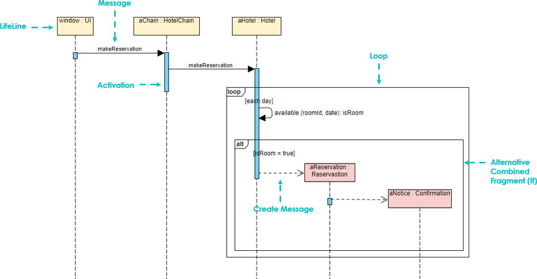
A Sequence Diagram, sometimes referred to as a sequential diagram, is a fundamental component of the Unified Modeling Language (UML) used to visualize the dynamic interactions between system components. Unlike static structure diagrams, sequence diagrams focus on the when and how of system behavior. They depict the temporal order of messages sent and received, illustrating the specific flow of control and data as objects collaborate to achieve a specific goal.
Whether you are designing a hotel reservation system or analyzing a complex microservice architecture, understanding sequence diagrams is crucial for modeling the chronological sequence of events.
The Core Elements of Sequence Diagrams
Building a sequence diagram involves assembling several key components that represent the participants and their interactions. These elements work together to create a visual narrative of a system’s execution.
1. Actors and Objects
The diagram begins by identifying the participants. An object in a sequence diagram is typically drawn as a rectangle containing its name, which is underlined. Objects can be named in three distinct ways, depending on the level of detail required:
- Object Name and Class: This format explicitly links a specific instance to its definition (e.g.,
aReservation : Reservation). - Anonymous Object: When the specific name is not important, only the class name is used (e.g.,
:Course). - Object Name Only: Sometimes, only the instance name is provided (e.g.,
lecturer).
Additionally, Actors are used to represent external entities that interact with the system. These can be human users, machines, or other subsystems.
2. Lifelines
Extending downwards from the object icon is a dashed vertical line known as the Lifeline. This line represents the existence of the object over time during the interaction. It indicates how long the object is active within the context of the sequence.
3. Focus of Control (Activation)
During an interaction, an object performs operations. This period of activity is called the Focus of Control or Activation. It is visually represented by a thin rectangle placed on the lifeline. This rectangle signifies the time period during which the object is performing an operation, analogous to a pair of brackets { } in C programming semantics. The top of the rectangle aligns with the initiation of the operation, and the bottom aligns with its completion.
4. Messages
Messages are the horizontal arrows that connect the objects, representing the flow of information. They are generally classified into three categories:
- Synchronous Message: The sender passes control to the receiver and waits for a return before continuing. It is depicted as a solid line with a solid arrowhead.
- Asynchronous Message: The sender passes a signal and continues its activity immediately without waiting for the receiver. This implies concurrent execution. It is depicted as a solid line with an open arrowhead.
- Return Message: This indicates the return from a procedure call. It is drawn as a dashed line with an open arrowhead pointing back to the sender.
Note on Instantaneous vs. Non-Instantaneous Messages: While messages are often drawn as horizontal lines implying they are instantaneous, you can use a slanted arrow to indicate that the message takes time to travel or process before the receiver actually receives it.
Advanced Concepts: Lifecycle and Logic
Sequence diagrams are powerful because they can model complex logic and object lifecycles.
Creation and Destruction
Objects do not always exist for the entire duration of the interaction. The diagram can show dynamic lifecycle management:
- Creation Messages: A constructor message creates a new receiver. Targets created during the interaction are placed further down the diagram than those existing at the start.
- Destruction Messages: An object can be destroyed using a destructor message, or by drawing an “X” at the end of the lifeline.
Combined Fragments
To handle complex logic such as loops, conditionals, or parallel processes, sequence diagrams use Combined Fragments. These are rectangular frames drawn over a portion of the diagram. The frame is labeled in the upper-left corner with an interaction operator:
- Loop: Indicates that a set of messages is repeated (e.g.,
[each day]). - Alt (Alternative): Represents conditional logic, similar to an
if-elsestatement. It allows you to specify different paths based on conditions (e.g.,[isRoom = true]). - Par (Parallel): Indicates that messages within the frame occur concurrently.
Best Practices for Ordering Objects
When arranging objects horizontally, the left-to-right order is not strictly defined by the UML standard. However, to ensure the diagram is clear and readable, you should follow these principles:
- Interaction Frequency: Place objects that interact frequently close together.
- Initialization: Place the object that initializes the entire interaction activity at the leftmost end.
Conclusion
Sequence diagrams provide a clear, temporal view of system interactions. By mastering elements like lifelines, activation bars, and combined fragments, you can effectively model complex system behaviors, from simple message passing to intricate conditional loops and object creation.