


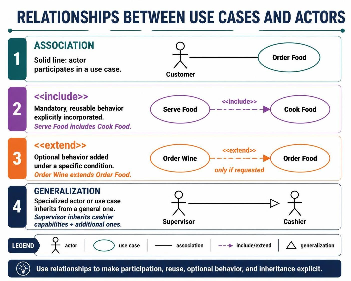
In the realm of software engineering and system analysis, the Use Case diagram is often the first bridge between business requirements and technical implementation. However, creating a diagram is not enough; understanding the semantics of the lines connecting your elements is what truly models a system accurately. Using tools like Visual Paradigm, developers can leverage standard UML relationships to define exactly how actors interact with the system and how use cases relate to one another.
This tutorial breaks down the four critical relationships depicted in the infographic: Association, Include, Extend, and Generalization. We will explore the logic behind each connection and how they contribute to a robust system architecture.
1. Association: The Foundation of Interaction
The most fundamental relationship in a Use Case diagram is the Association. In the context of Visual Paradigm, this is represented by a solid line connecting an Actor to a Use Case.
- Semantics: This line indicates a direct participation. It answers the question: “Who does this?” If a line exists between the Customer actor and the Order Food use case, it signifies that the Customer is the primary agent initiating or interacting with that specific functionality.
- Directionality: While often drawn as a solid line, UML allows for navigation properties (open vs. closed arrowheads) to indicate the direction of the information flow, though the basic association implies a bidirectional interaction capability.
Without Associations, your diagram is merely a list of features without context. They are the threads that weave the actors into the fabric of the system.
2. Include Relationships: Mandatory Reusability
As systems grow in complexity, functionality often repeats itself. The «include» relationship is your tool for enforcing modularity and mandatory steps. It represents a dependency where one use case (the base) explicitly incorporates the behavior of another (the included use case).
Consider the logic of a restaurant system. The use case Serve Food cannot exist without the use case Cook Food. In Visual Paradigm, this is modeled using a dashed line with a hollow arrowhead pointing from the base use case to the included one.
' Logic Example
UseCase "Serve Food" as ServeFood
UseCase "Cook Food" as CookFood

ServeFood ..> CookFood : <>
When implementing this, remember that the included use case is mandatory. The flow of control will automatically pass through the included step every time the base use case is executed. This is ideal for breaking down complex processes into smaller, reusable sub-processes.
3. Extend Relationships: Optional Behavior and Conditions
While «include» handles mandatory steps, the «extend» relationship handles the “what if” scenarios. It allows you to define optional behavior that is added to a base use case only under specific conditions.
Looking at the diagram, we see Order Wine extending Order Food. The condition here is “only if requested.” This means that while a customer can successfully execute “Order Food” without ever interacting with “Order Wine,” the system must be prepared to handle the extension if the condition is met.
- Direction of Dependency: Unlike inclusion, the arrow for extension points from the extending use case to the base use case.
- Extensibility: This relationship is powerful for modeling exception handling, error messages, or premium add-ons without cluttering the main flow of the base use case.
4. Generalization: Inheritance in Actors and Use Cases
The final relationship, Generalization, introduces the concept of inheritance to your Use Case diagram. This is visually represented by a solid line with a hollow, triangular arrowhead.
In the context of the image, the Supervisor actor is a specialized version of the Cashier actor. This implies that the Supervisor inherits all the capabilities of a Cashier but also possesses additional, specific capabilities.
' Logic Example
Actor "Cashier" as Cashier
Actor "Supervisor" as Supervisor

Supervisor --|> Cashier : generalization
This relationship is highly efficient for modeling user roles. Instead of drawing separate lines for every function a Supervisor can perform (like “Approve Refund”), you can simply state that the Supervisor is-a Cashier, thereby inheriting the “Process Payment” capability automatically.
Conclusion: Using Relationships Explicitly
The goal of these relationships is not just to draw lines between ovals and stick figures, but to make the system logic explicit. By distinguishing between mandatory steps («include»), optional steps («extend»), and role inheritance (Generalization), you create a blueprint that developers can implement with confidence. Visual Paradigm provides the environment to visualize these complex interactions clearly, ensuring that the transition from design to code remains seamless.