


In the world of software engineering, communication is key. But how do developers and architects communicate the precise timing and order of operations between different system components? The answer lies in Sequence Diagrams. These dynamic models are essential for illustrating the flow of messages between objects for critical business processes, providing a visual narrative of how a system behaves over time.
In this tutorial, we will deconstruct a complex Sequence Diagram, exploring the anatomy of interaction frames, guards, and combined fragments. We will walk through the concepts step-by-step, demonstrating how to model logic like loops and conditional breaks using industry-standard notation.
Understanding the Core Components
Before diving into the logic, we must understand the building blocks that make up a sequence diagram. Every interaction diagram relies on a few fundamental elements to tell the story of a system.
1. Lifelines and Activation
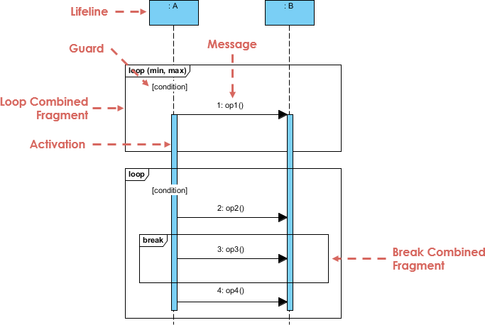
The vertical dashed lines at the top of the diagram represent Lifelines. These are the participants in the interaction—typically objects, classes, or external systems (labeled here as :A and :B). Attached to these lifelines are the thin, vertical rectangles known as Activation Bars (or execution occurrences). An activation bar indicates the period during which an object is performing an action, waiting for a response, or holding the CPU’s attention.
2. Messages
The horizontal arrows connecting the activation bars represent Messages. These are the signals sent from one object to another. The sequence is chronological: the top of the diagram happens first, and time flows downwards. Messages can be synchronous (waiting for a reply), asynchronous (sending and forgetting), or return messages.
Modeling Logic with Combined Fragments
Real-world systems are rarely linear. They involve loops, choices, and conditions. In UML, we use Combined Fragments to encapsulate these complex behaviors. These are the rectangular frames that group specific interactions together.
The Loop Fragment
One of the most common requirements in system design is iteration. The Loop combined fragment allows us to model a block of interaction that repeats. In our diagram, the first frame is labeled loop with the syntax (min, max). This indicates how many times the contained messages should occur.
Notice the Guard condition, denoted by [condition] inside square brackets. This is a Boolean expression that must evaluate to true for the loop to continue or for the loop to execute at all. If the condition fails, the system exits the loop.
The Break Fragment
Sometimes, a loop must be interrupted prematurely. This is where the Break combined fragment shines. In the lower section of our diagram, we see a nested frame labeled break. This fragment represents an alternative path that, if triggered, causes the execution of the surrounding interaction (like the outer loop) to be terminated immediately.
Putting It All Together: A Logic Walkthrough
Let’s trace the flow of the diagram to understand the complete logic of this system interaction.
- Initiation: The process begins with
:Asending a message1: op1()to:Bwithin the initial loop frame. - Looping: If the
[condition]for the loop is met, the system repeats the operation.:Asends2: op2()to:B. - Conditional Interruption: Inside the loop, a Break frame is active. If a specific trigger occurs (implied by the frame’s existence), the system executes
3: op3(). This action signifies a break condition. - Termination: Once the break condition is met, the loop is terminated. The system proceeds to execute
4: op4(), which lies outside the break frame but follows the loop logic.
Tooling: Visual Paradigm
Creating accurate and professional sequence diagrams requires the right tools. For this tutorial, we utilize Visual Paradigm. This comprehensive modeling platform is designed to handle complex UML specifications, allowing users to easily define combined fragments, add guards, and manage lifelines with precision.
Visual Paradigm provides an intuitive interface for dragging and dropping these structural elements, ensuring that your diagrams are not only logically sound but also visually clear. By relying on this dedicated tooling, you ensure that your documentation aligns with the highest standards of software architecture.
Conclusion
By mastering the use of lifelines, activation bars, and combined fragments, you gain the ability to model even the most intricate business processes. Whether you are defining a simple login sequence or a complex financial transaction loop, the principles of sequence diagrams remain the same: clarity, precision, and a logical flow of time.