Business Process Model and Notation (BPMN) is the universal standard for visualizing complex workflows. However, just because a tool allows you to drag and drop shapes onto a canvas does not mean the resulting diagram accurately represents the business logic. A poorly constructed BPMN diagram can lead to development errors, automation failures, and miscommunication between business stakeholders and technical teams.
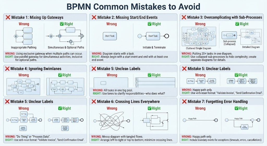
As a technical tutor, I often see diagrams that look “correct” at a glance but fail under scrutiny. This tutorial breaks down seven common mistakes found in BPMN modeling, providing the architectural context and the correct patterns to ensure your process models are robust, scalable, and clear.
1. The Gateway Logic Trap
Gateways control the flow of the process. Misusing them is the most frequent cause of logic errors. The fundamental mistake is assuming that only one path can ever be taken, regardless of the data context.
The Exclusive Gateway Fallacy
Using an Exclusive Gateway (the diamond shape with the ‘X’) implies that the process must choose one path and ignore the others. If you model a scenario where multiple conditions can be true simultaneously—such as a customer qualifying for both a “Discount” and a “Free Shipping” option—an exclusive gateway will force the modeler to arbitrarily pick one path, breaking the logic.
The Parallel and Inclusive Solution
To resolve this, you must distinguish between simultaneous execution and optional execution:
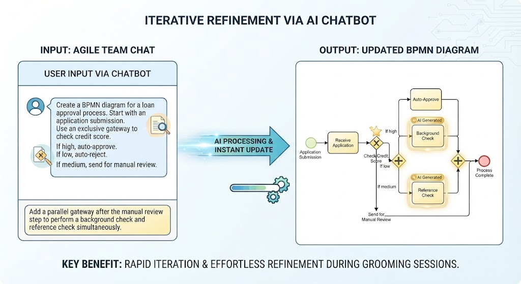
- Parallel Gateway (+): Use this when multiple activities must happen at the same time. It splits the flow into multiple branches that execute concurrently and waits for all to finish before merging.
- Inclusive Gateway (Circle with #): Use this for optional paths. If Condition A is met, path A runs. If Condition B is met, path B runs. If both are met, both paths run. This is the most versatile gateway for complex business rules.
2. The “Start Task” Antipattern
One of the most glaring errors in novice diagrams is starting the flow directly with a Task (a rectangle with rounded corners). In BPMN, a task is an action, not an initiation point.
Why It Matters
Without a proper Start Event, the process definition lacks a trigger. Is this task triggered by a timer? A message from an external system? A manual user initiation? The diagram implies the task just exists, which is technically invalid.
The Correct Architecture
Every robust process must have a defined entry point. Always wrap your first task with a Start Event (usually a circle). Similarly, ensure you have at least one End Event. A process that ends with a task leaves the system in an undefined state—did it succeed? Did it fail? Was it cancelled? Always terminate with an End Event to signal completion.
3. The “Spaghetti” Sub-Process
As processes grow, so does the complexity. A common mistake is trying to cram 20+ tasks into a single canvas. This results in a “spaghetti diagram” that is impossible to read, debug, or maintain.
Context vs. Detail
Think of your diagrams like a map. You wouldn’t show the street-level details of a city on a map of a continent. Similarly, you should not show the granular task details of a sub-process within the high-level view.
The Abstraction Pattern
Use Collapsed Sub-Processes. In the high-level context diagram, represent a complex section as a single, collapsed box. This hides the internal complexity and allows the reader to focus on the main flow. If a stakeholder needs to understand the details of that specific section, they can open the sub-process diagram. This creates a modular architecture that scales infinitely.
4. Ignoring Swimlanes (Pools and Lanes)
A diagram containing a single “Pool” with all tasks inside is a recipe for confusion. Without swimlanes, the diagram answers “what happens” but fails to answer “who is responsible.”
The Accountability Gap
In a large organization, a task like “Approve Invoice” might involve the Manager, the Finance Team, and the System. If these are all in one big pool, the handoffs are invisible.
Clarifying Responsibilities
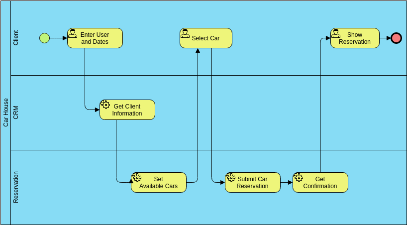
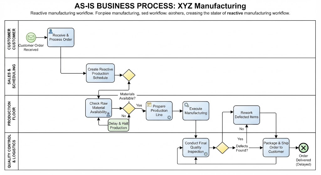
Use Swimlanes (Lanes) to segregate activities by role, department, or system. This creates a visual boundary that clarifies ownership. It also makes it easier to spot handoff points where information moves from one actor to another, which are critical points for potential bottlenecks.
5. The “Verb-Noun” Labeling Rule
Labels are the interface between the diagram and the human reader. Vague labels like “Do Thing,” “Process Data,” or “Update Status” are the enemies of clarity. They force the reader to guess the intent.
Specificity is Key
Every label should be a specific action. The industry standard is to use the Verb-Noun format.
- Weak: “Check Data”
- Strong: “Validate Invoice”
- Weak: “Send Message”
- Strong: “Send Confirmation Email”
Specific verbs (Validate, Send, Calculate, Generate) combined with specific nouns (Invoice, Report, User) eliminate ambiguity regarding the scope of the task.
6. The Crossing Lines Error
While a diagram might function logically even with tangled lines, aesthetics play a huge role in cognitive load. A diagram with crossing lines everywhere is difficult to trace. It forces the eye to jump over obstacles, increasing the chance of missing a connection.
Visual Flow Principles
Good diagramming follows the natural reading order: Left-to-Right or Top-to-Bottom.
Minimize Cognitive Load
When arranging your diagram, prioritize layout over immediate content. If you have to cross a line, ask yourself: “Can I rearrange these tasks?” or “Can I add a flow marker to make the path clearer?” A clean diagram is a self-documenting diagram.
7. The “Happy Path” Blind Spot
This is the most dangerous mistake because it creates a false sense of security. Many diagrams only show the “Happy Path”—the scenario where everything goes perfectly. They assume inputs are valid, servers are online, and users click the right buttons.
Reality is Messy
Real-world systems deal with timeouts, network failures, invalid data, and user cancellations. If your BPMN diagram doesn’t account for these, the developers will build a system that crashes the first time an exception occurs.
Boundary Events for Robustness
Always include Boundary Events attached to your tasks. These are small circles on the edge of a task that intercept errors. For example, attach a timer boundary event to a “Wait for Payment” task to handle timeouts, or an error boundary event to handle invalid data input. This ensures your architecture is resilient.
Conclusion
Modeling is not just about drawing boxes; it is about defining the logic, responsibilities, and error handling of a system. By avoiding these seven common mistakes—mixing up gateways, skipping events, overcomplicating diagrams, ignoring swimlanes, using vague labels, creating messy layouts, and ignoring errors—you will produce professional-grade BPMN models that drive successful business automation.