Knowing how the business operates is the first and most critical step of business process improvement. However, describing complex workflows in text often leads to misunderstandings between business analysts and stakeholders. This is where Business Process Model and Notation (BPMN) becomes essential. BPMN provides a graphical representation of business workflows that anyone can easily understand, serving as a universal language to aid in business process analysis and improvements.
Any process described with BPMN is represented as a number of steps, or activities, that are performed consecutively or simultaneously according to certain business rules. To truly grasp these concepts, we must look at a concrete example of a cross-functional process.
The Anatomy of a BPMN Diagram
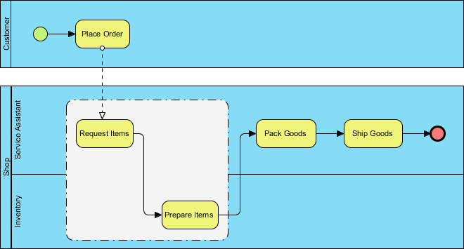
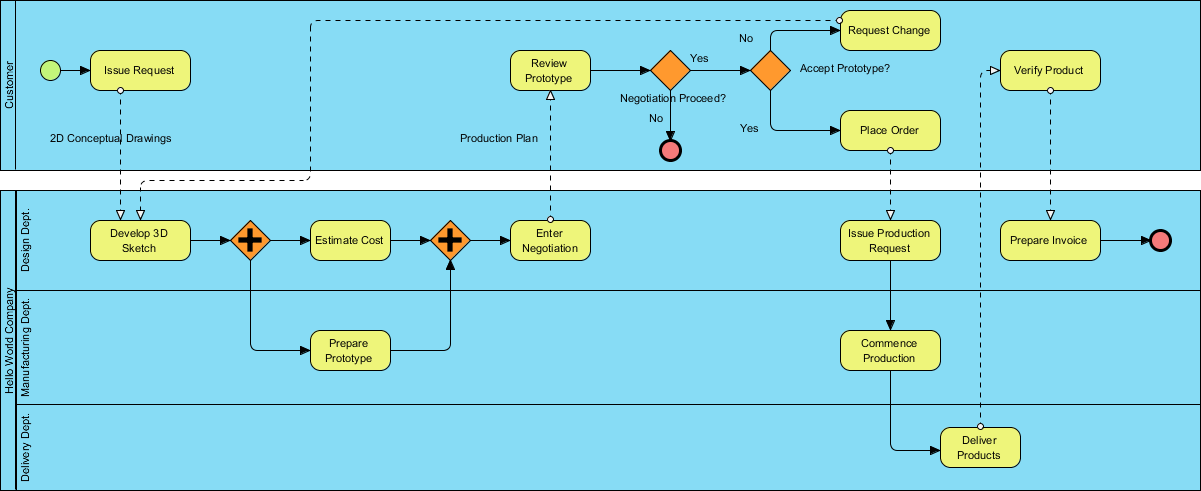
When you look at a BPMN diagram, you are essentially looking at a map of a journey. The map is divided into sections, just like a highway system, to show who is responsible for what. In the visual example we are discussing, the diagram is divided into swimlanes representing different departments or actors: the Customer, the Design Department, the Manufacturing Department, and the Delivery Department.
Here are the key concepts that bring this diagram to life:
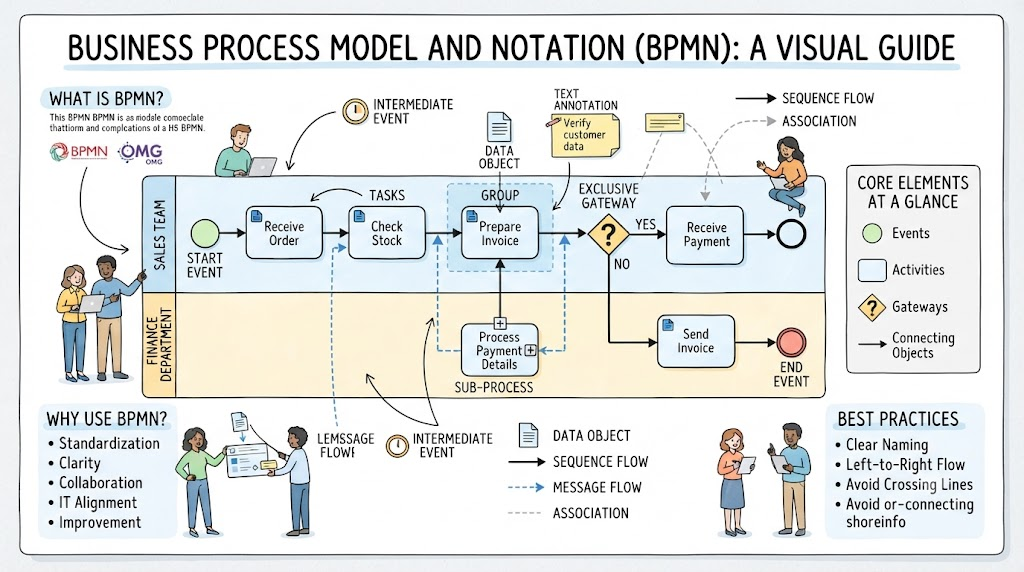
- Tasks (Activities): Represented by rounded rectangles, these are the specific actions taken, such as “Issue Request,” “Develop 3D Sketch,” or “Place Order.”
- Gateways: These are the decision points. The orange diamonds in the diagram represent gateways. For instance, the “Negotiation Proceed?” diamond determines the path of the process. If the answer is “No,” the process ends (the red circle). If “Yes,” it moves forward.
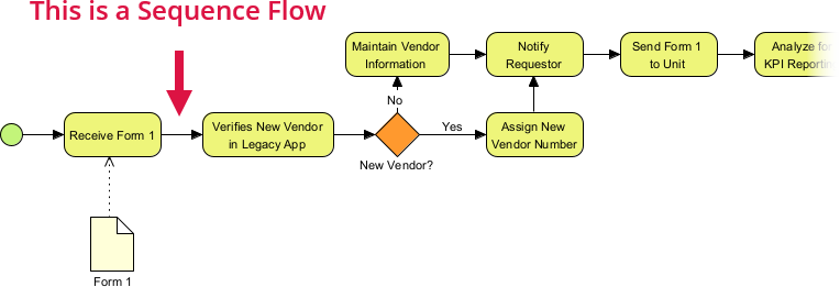
- Sequence Flow: The solid arrows connecting the tasks show the order of execution.
- Parallel Gateways: You might notice the orange diamonds with a plus sign (+). These indicate that multiple paths happen simultaneously. In our example, after “Develop 3D Sketch,” the process splits to “Estimate Cost” and “Prepare Prototype” at the same time, speeding up the workflow.
Walking Through the “Request Change” Process
Let us trace the flow of the “Request Change” process shown in the diagram. It begins in the Customer lane with the activity Issue Request. This triggers a dashed line, representing a message flow, which travels down to the Design Department’s lane to begin Develop 3D Sketch.
Once the sketch is ready, the process hits a parallel gateway. The system estimates the cost while simultaneously preparing a prototype. Both of these paths must complete before the flow merges again at the next gateway, leading to Enter Negotiation. This is a crucial business rule: you cannot negotiate until you have both a cost estimate and a physical prototype.
From there, the process hits an exclusive gateway asking, Negotiation Proceed?. If the negotiation fails (No), the process terminates. If it succeeds (Yes), the Customer reviews the prototype. If the prototype is accepted, the flow moves to Place Order. This triggers the Manufacturing Department to issue a production request and commence production. Finally, the Delivery Department takes over to deliver the products, concluding with a final red circle event.
Visual Paradigm: Bringing Your Models to Life
While understanding the theory is vital, the practical application requires the right tools. Visual Paradigm is a comprehensive modeling tool that simplifies the creation of these complex diagrams. It allows you to drag and drop elements onto the canvas, automatically handling the alignment and logic connections, which saves hours of manual drawing.
One of the standout features of Visual Paradigm is its ability to integrate Artificial Intelligence (AI) to make BPMN more agile. In the past, business processes were modeled as static, rigid diagrams. Today, with AI assistance in Visual Paradigm, you can generate user stories directly from your BPMN models. This bridges the gap between high-level business strategy and the agile development teams building the software to support it.
Furthermore, Visual Paradigm supports the “Agile” mindset by allowing you to manage the lifecycle of your process. Instead of a diagram gathering dust, it becomes a living document. You can link tasks in your BPMN diagram to actual work items in your project management tools. This ensures that if a business rule changes—say, the “Negotiation Proceed?” criteria shifts—the model updates, and the development team is immediately notified.
Conclusion
Mastering BPMN is about more than just drawing boxes and arrows; it is about clarifying how value is delivered to the customer. By using a robust tool like Visual Paradigm, you ensure that your diagrams are not only accurate representations of reality but also agile assets that drive continuous improvement in your organization.