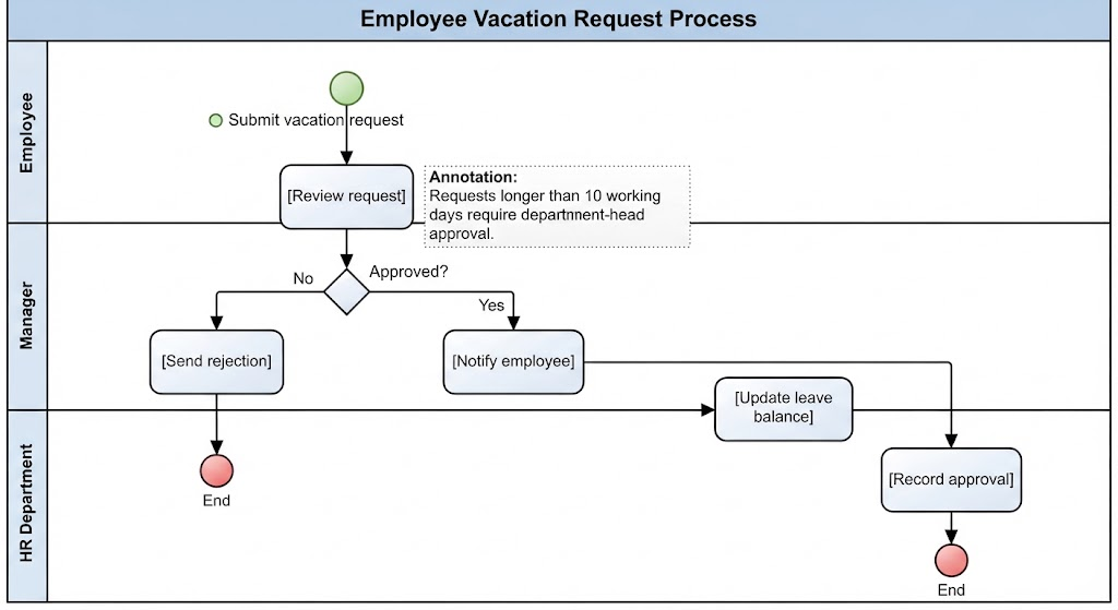
In the realm of business process management, clarity is currency. A well-defined process model does more than just show a sequence of steps; it acts as a blueprint for organizational efficiency, clarifying roles, responsibilities, and decision logic. This tutorial explores the architecture of a classic business scenario: the Employee Vacation Request Process.
We will dissect the provided diagram to understand how Business Process Model and Notation (BPMN) handles Swimlanes, Gateways, and the critical distinction between Annotations and Decision Paths. By the end of this guide, you will understand how to translate a textual business rule into a robust, executable technical model.
Understanding the Swimlane Architecture
The diagram utilizes a Swimlane Diagram structure. This visual metaphor is essential for enterprise modeling because it assigns ownership to specific tasks. In our Vacation Request scenario, the vertical lanes represent three distinct actors:
- Employee: The initiator of the process who triggers the workflow.
- Manager: The approver responsible for the quality control of the request.
- HR Department: The backend system or administrator responsible for data integrity.
By segregating these lanes, the model enforces the concept of separation of duties. The Employee cannot approve their own request, and the HR system cannot initiate the request. This structure is vital for audit trails and compliance.
The Anatomy of the Workflow
The process flow can be broken down into three distinct phases: Initiation, Decision, and Execution.
1. Initiation Phase
The process begins with a Start Event, represented by the green circle labeled “Submit vacation request.” This is a signal that a specific instance of the process is being created. Following this, the Manager performs the task “[Review request].” This task is the entry point for the decision logic.
2. The Decision Gateway
One of the most critical elements in the diagram is the diamond shape labeled “Approved?”. In BPMN, this is a Exclusive Gateway (XOR Gateway). It represents a point where the process flow splits based on a condition.
The gateway creates two distinct paths:
- The “No” Path: If the request is rejected, the flow moves to “[Send rejection]” and terminates at the red circle “End.”
- The “Yes” Path: If approved, the flow moves to “[Notify employee]” and proceeds to HR tasks.
3. The Execution Phase (HR)
Once the decision is positive, the workflow crosses the swimlane boundary into the HR Department. This illustrates handoffs between departments. The HR tasks involve data manipulation:
- [Update leave balance]: Adjusting the employee’s account.
- [Record approval]: Archiving the decision for compliance.
Modeling Complex Business Rules: Annotations vs. Gateways
The diagram includes a powerful lesson on how to handle conditional logic. Notice the dotted box attached to the “Review request” task:
Annotation: Requests longer than 10 working days require department-head approval.
This presents a modeling dilemma. How do we represent the fact that some requests need extra approval? There are two ways to model this, but they have vastly different implications for the system’s execution.
The Annotation Approach (Static)
In the current diagram, the rule is written as an Annotation. An annotation is a comment. It provides context to the human reader but does not alter the technical flow of the diagram. If a software engine were to execute this diagram, it would ignore the annotation and simply route the request to the “Approved?” gateway regardless of the duration.
The Gateway Approach (Dynamic)
If the rule “Requests longer than 10 working days require department-head approval” is a hard constraint that must be enforced by the system, the annotation is insufficient. As noted in the supplementary context: “If the rule creates another decision path, it should be modeled with a gateway rather than only written as an annotation.”
To make this rule executable, the modeler should introduce a second Gateway immediately after “[Review request].” The logic would be:
- Is duration > 10 days?
- Yes: Route to Department Head Approval.
- No: Route to Manager Approval (the standard path).
Recommended Tooling: Visual Paradigm BPMN and AI
Modeling these architectures requires precision. A single misplaced line can lead to ambiguity in business logic. For this tutorial, we recommend using Visual Paradigm BPMN as the primary tooling solution.
Visual Paradigm offers:
- Drag-and-Drop Swimlanes: Intuitive placement of lanes for Employee, Manager, and HR.
- Smart Routing: Automatic alignment of connectors to ensure the diagram remains clean.
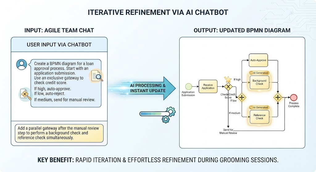
- AI Integration: Modern versions of Visual Paradigm leverage AI to assist in diagramming. AI features can help generate process flows from textual descriptions (like the one in our context) or suggest optimizations for the diagram layout.
By combining the structural clarity of BPMN with the intelligent assistance of AI-driven tools, organizations can ensure their process models are not just theoretical diagrams, but accurate representations of their operational reality.
Conclusion
The Employee Vacation Request diagram serves as a foundational example of process engineering. It demonstrates the importance of separating concerns via swimlanes and handling decision points with Exclusive Gateways. Furthermore, it highlights the necessity of distinguishing between informational annotations and executable logic gates.
To replicate and enhance such models effectively, we strongly recommend adopting Visual Paradigm BPMN for its robust modeling capabilities and AI features for accelerating the design and validation of complex business rules.