In the world of Business Process Model and Notation (BPMN), clarity is king. When you look at a complex diagram, the most critical element that ties everything together is the Sequence Flow. It is the invisible highway that dictates the order of operations, ensuring that a process moves logically from a starting point to a successful conclusion.
This tutorial breaks down the anatomy of Sequence Flow using a practical example: a vendor onboarding process. By the end of this guide, you will understand not just how to draw it, but how it drives the “token”—the execution unit—through your system.
What is a Sequence Flow?
At its core, a Sequence Flow represents the order in which steps or activities are executed. Think of it as the arrow on a treasure map. Without the arrows, the X marks the spot, but you don’t know which path to take to get there.
- The Driver: It is the primary driver of control flow within a process.
- The Scope: It is strictly used inside a single pool or lane. This is a critical distinction. If you draw a line across the boundary of a pool, you are no longer describing internal control; you are describing communication between different systems or people.
- The Token: In BPMN theory, a “token” travels along the sequence flow. When an activity finishes, the token moves along the sequence flow to the next node.
Visual Anatomy: Decoding the Diagram
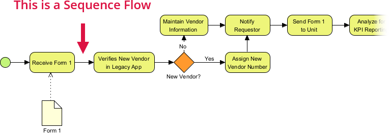
Let’s analyze the vendor onboarding process shown above. We can break the sequence flow down into four distinct types of nodes connected by these flow lines.
1. The Start Event
The process begins at the green circle on the far left. This is the Start Event. It signifies the trigger for the process. In this specific case, the process is triggered by the arrival of a document, indicated by the data object (the paper icon labeled “Form 1”) attached via a dashed line.
2. The Tasks (Activities)
The rounded rectangles represent Tasks. These are the actions performed by a human or a system. The sequence flow connects them in a linear fashion:
- Receive Form 1: The initial intake.
- Verifies New Vendor in Legacy App: A system check.
- Assign New Vendor Number: A specific administrative task.
- Notify Requestor: A communication step.
- Send Form 1 to Unit: The transfer of data.
- Analyze for KPI Reporting: The final analysis task.
3. The Gateway (The Decision Point)
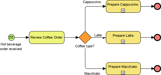
The orange diamond labeled “New Vendor?” is a Gateway. This is where the Sequence Flow splits. A gateway does not perform work; it determines the path. The type of gateway dictates how the sequence flow behaves:
- Exclusive Gateway: In this diagram, the diamond acts as a decision point. Only one path can be taken. The token must choose either “Yes” or “No”.
- Labeling Paths: Notice the text labels on the arrows. The arrow pointing right is labeled “Yes”, and the arrow pointing up is labeled “No”. These labels define the condition required to traverse that specific sequence flow.
Walking Through the Logic: A Step-by-Step Flow
To truly understand sequence flow, we must simulate the execution of the token. Here is how the process unfolds:
- Initiation: The token starts at the green circle and moves right to Receive Form 1.
- Verification: The flow continues to Verifies New Vendor in Legacy App.
- The Decision: The token hits the New Vendor? gateway.
- Scenario A (Yes): If the vendor is new, the token follows the “Yes” arrow to Assign New Vendor Number.
- Scenario B (No): If the vendor already exists, the token follows the “No” arrow to Maintain Vendor Information.
- Merging Paths: This is a crucial concept in sequence flow. Both the “Yes” path (after notifying) and the “No” path (after maintaining info) eventually converge at the Notify Requestor task. This is known as a merge. The process effectively says, “Regardless of whether you are new or existing, you must be notified now.”
- Completion: The flow proceeds linearly to Send Form 1 to Unit and finally Analyze for KPI Reporting.
Technical Implementation Tips
When modeling this in tools like Visual Paradigm, there are specific behaviors you must adhere to to ensure your diagram is valid and readable.
Automated Creation
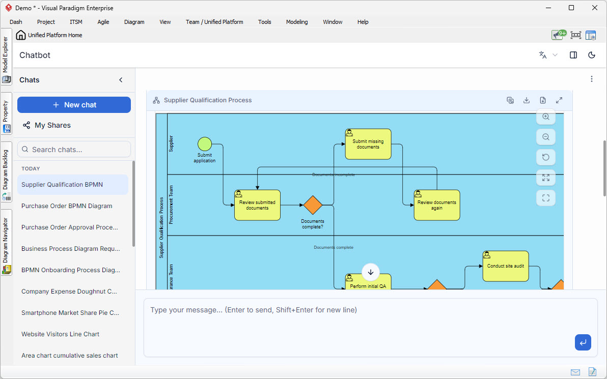
Most modern modeling tools are intelligent. When you drag a connector from one shape to another within the same pool, the software automatically creates a Sequence Flow. You do not need to manually select “Sequence Flow” from a palette every time.
Avoiding Validation Errors
A common pitfall for beginners is dragging a connector across pool lines.
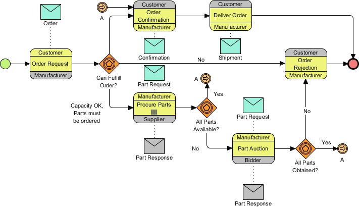
Warning: Ensure you do not accidentally drag a sequence flow across pool lines. In BPMN, crossing pool boundaries requires a Message Flow (usually a dashed line), not a Sequence Flow. Attempting to use a solid sequence flow to cross pools will result in a validation error because it implies a single system is controlling two separate entities, which violates the architecture.
Conclusion
The Sequence Flow is the backbone of any BPMN diagram. It transforms a static collection of shapes into a dynamic representation of reality. By understanding how tokens move from Start Events, through Tasks and Gateways, and eventually to End Events, you can design robust, error-free business processes.