


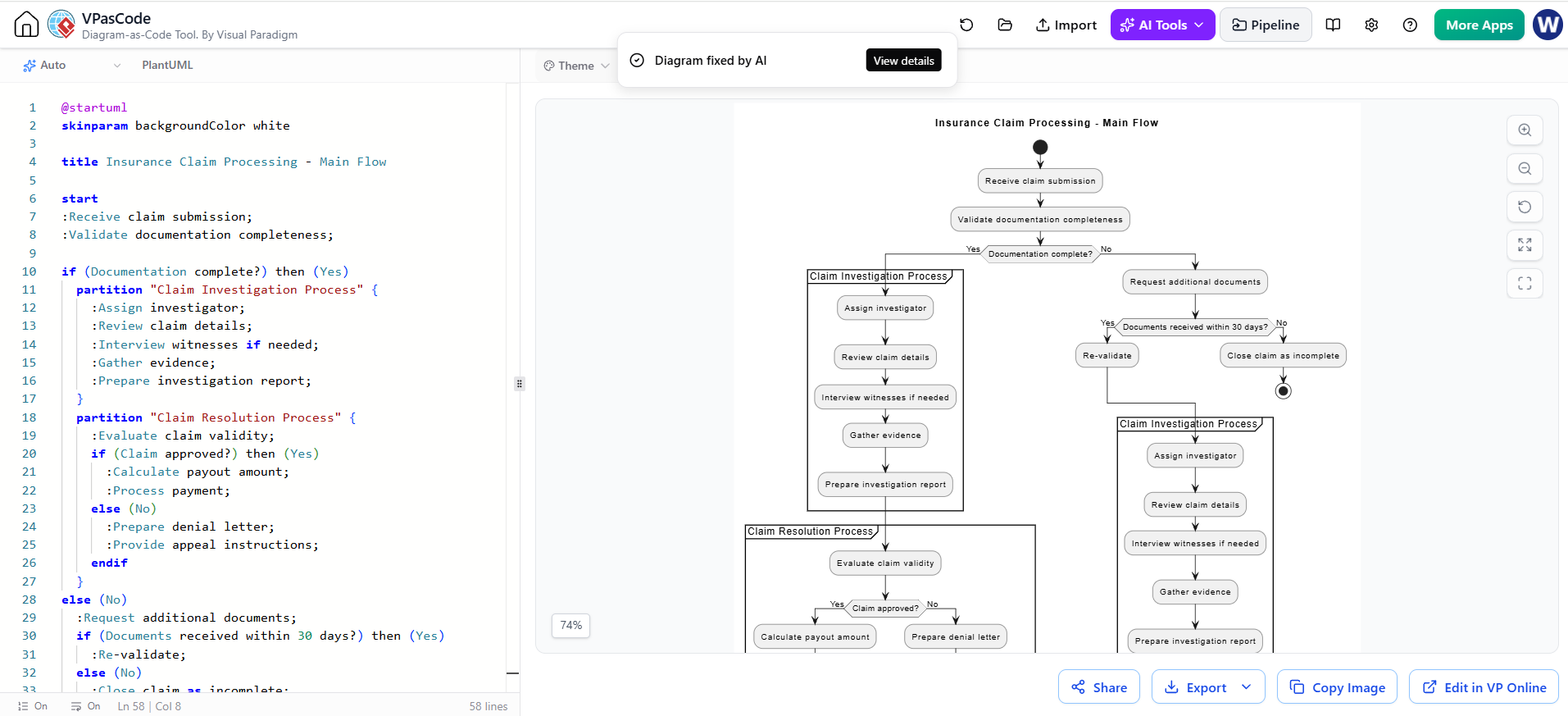
In the realm of business process modeling, few tasks are as critical—and as complex—as visualizing an insurance claim lifecycle. The transition from raw data to a rendered diagram can often be a hurdle for technical writers and analysts. This tutorial bridges that gap by exploring how to leverage VPasCode (Visual Paradigm’s Diagram-as-Code tool) to architect a robust PlantUML activity diagram. We will dissect the architecture of a claim processing system, focusing on how to handle conditional logic, nested sub-processes, and state management within a code-driven workflow.
The Architecture of a Claim Processing System
Before writing a single line of code, we must understand the logical flow of the system. An insurance claim is not merely a linear path; it is a decision tree where the state of the data determines the next step. Our target architecture involves three distinct phases:
- Ingestion & Validation: The system receives a claim and performs an immediate sanity check on the documentation.
- Investigation: If the claim is valid, it enters a deep-dive phase involving investigators and evidence gathering.
- Resolution: The final stage where the claim is either approved for payout or denied with an appeal process.
The challenge lies in modeling the Sub-Processes. In our diagram, “Investigation” and “Resolution” are not just single steps; they are encapsulated workflows. VPasCode allows us to treat these as partitions, keeping the main flow clean while defining internal complexity.
Code-Driven Modeling with VPasCode
Visual Paradigm’s VPasCode utilizes the PlantUML syntax, a text-based language that describes diagrams. This approach offers version control and ease of editing compared to drag-and-drop interfaces. Below is the breakdown of the specific syntax used to model this complex flow.
1. Setting the Stage: Skinparams and Titles
The diagram begins with configuration. We define the visual theme and the title to ensure the output is professional and self-explanatory.
@startuml
skinparam backgroundColor white
title Insurance Claim Processing - Main Flow
The skinparam directive is crucial for branding. By setting backgroundColor white, we ensure the diagram renders cleanly for reports or web embedding.
2. Defining the Main Flow and Decision Nodes
The core logic starts with the start keyword. We then move through the initial validation. The first major decision point checks if the documentation is complete. In PlantUML, we use the if (condition) then (outcome) syntax to create branches.
@startuml
skinparam backgroundColor white
title Insurance Claim Processing - Main Flow
start
:Receive claim submission;
:Validate documentation completeness;
if (Documentation complete?) then (Yes)
  // ... Logic for complete claims
else (No)
  // ... Logic for incomplete claims
endif
stop
@enduml
3. Encapsulating Sub-Processes with Partitions
This is the most advanced concept in our tutorial. To model a complex process within a single step, we use the partition keyword. This creates a visual box that groups related activities.
In the “Yes” branch of our logic, we need to investigate. Instead of listing every step on the main line, we encapsulate them:
@startuml
skinparam backgroundColor white
title Insurance Claim Processing - Main Flow
start
:Receive claim submission;
:Validate documentation completeness;
if (Documentation complete?) then (Yes)
partition "Claim Investigation Process" {
  :Assign investigator;
  :Review claim details;
  :Interview witnesses if needed;
  :Gather evidence;
  :Prepare investigation report;
}
partition "Claim Resolution Process" {
  :Evaluate claim validity;
  if (Claim approved?) then (Yes)
    :Calculate payout amount;
    :Process payment;
  else (No)
    :Prepare denial letter;
    :Provide appeal instructions;
  endif
}
else (No)
  // ...
endif
stop
@enduml
Notice how the partition block contains its own internal logic. This modularizes the diagram, allowing the “Claim Investigation Process” to be expanded later into a separate diagram if necessary.
Handling Nested Logic and State Management
The “No” branch of the initial validation introduces a secondary state machine. If documentation is missing, the system requests more documents and starts a timer (conceptually).
@startuml
skinparam backgroundColor white
title Insurance Claim Processing - Main Flow
start
:Receive claim submission;
:Validate documentation completeness;
if (Documentation complete?) then (Yes)
  // ...
else (No)
  :Request additional documents;
  if (Documents received within 30 days?) then (Yes)
    :Re-validate;
  else (No)
    :Close claim as incomplete;
    stop
  endif
endif
stop
@enduml
This nested if statement demonstrates how VPasCode handles depth. The logic flows naturally, but visually, it creates a clear “Request -> Wait -> Decide” loop. If the 30-day window expires, the process terminates with a stop node, ensuring the diagram represents a finite state machine.
Interpreting the Generated Diagram
Once the code is submitted to VPasCode, the AI engine and rendering engine process the text. The resulting diagram, as seen in the preview, provides a clear, top-down view of the workflow. It effectively communicates the following:
- Clear Entry and Exit Points: The
startandstopnodes define the lifecycle boundaries. - Conditional Routing: The decision diamonds clearly show the “Yes/No” paths for documentation and approval.
- Process Grouping: The partitions visually separate the administrative tasks from the investigative and resolution tasks.
By mastering these syntax elements—skinparam, partition, and nested if statements—you can transform complex business requirements into clean, actionable technical diagrams using text alone.