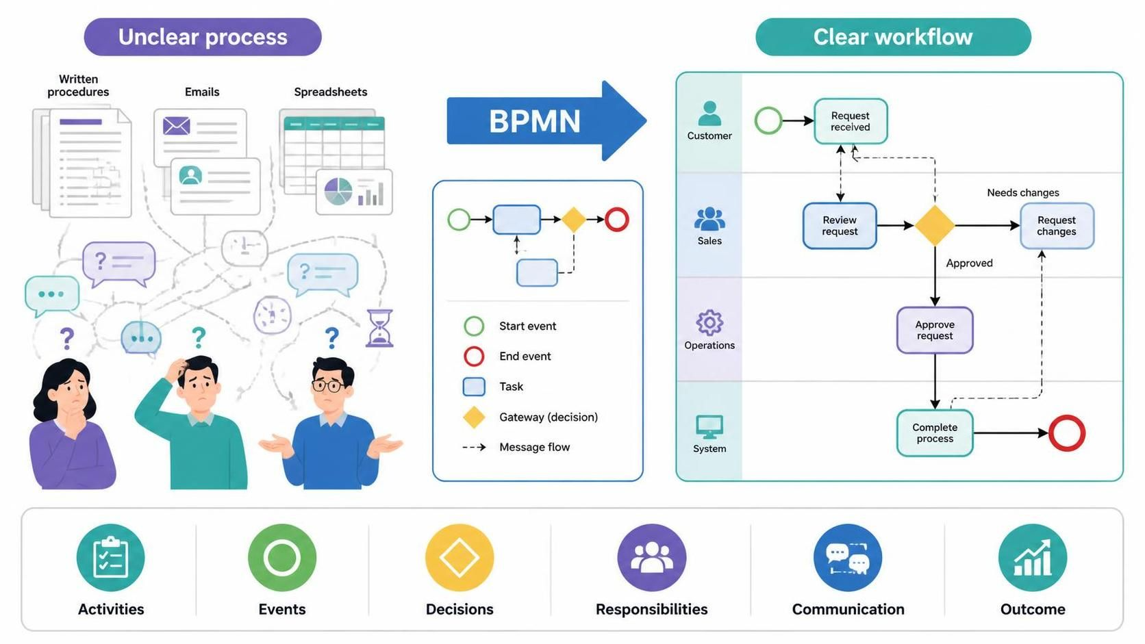
In the modern enterprise, business processes are rarely linear. They involve complex interactions between different departments, external customers, and automated systems. When these workflows are documented only in static text, emails, or scattered spreadsheets, they often become sources of confusion. This “Unclear process” state is characterized by ambiguity regarding who is responsible for what and how exceptions are handled.
The solution lies in Business Process Model and Notation (BPMN). As the industry standard for process modeling, BPMN transforms abstract descriptions into a structured visual language. This tutorial explores the transition from an unstructured workflow to a “Clear workflow” using BPMN, analyzing the specific components—Activities, Events, Decisions, and Communication—that make a process transparent and actionable.
The Anatomy of a Clear Workflow
To understand how BPMN solves the problem of complexity, we must look at the specific visual elements used in the “Clear workflow” diagram. These elements break down a complex business scenario into logical, manageable steps.
1. Activities and Responsibilities (Swimlanes)
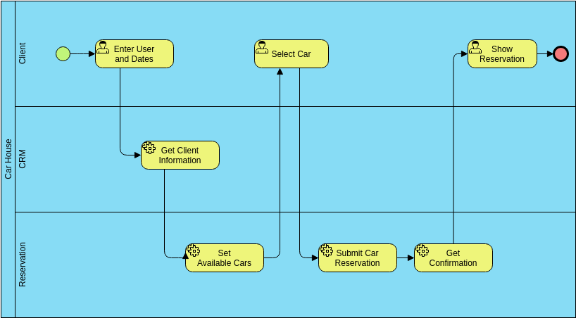
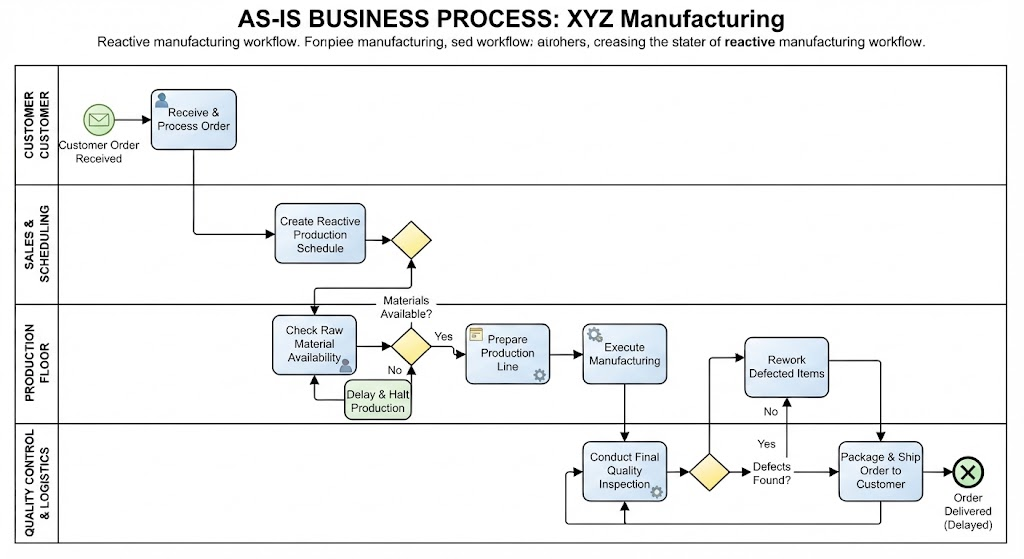
One of the most powerful features of BPMN is the use of Swimlanes. In a clear workflow diagram, the vertical lanes represent specific “Responsibilities” or roles within the organization. This structure ensures that every task is explicitly assigned to an entity.
- Customer: The external actor initiating the work.
- Sales: The department responsible for the initial review.
- Operations: The team handling the core approval and execution logic.
- System: Automated components or software handling the final completion.
2. Events (Start, Intermediate, End)
Events act as the triggers and outcomes of the process. They are represented by circles in BPMN:
- Start Event (Green Circle): Marks the beginning of the workflow. In our example, the process begins when a “Request received” event occurs.
- End Event (Red Circle): Marks the termination of the process. The workflow concludes with the “Complete process” event.
3. Decisions (Gateways)
Real-world processes are rarely straight lines; they require decisions. In BPMN, these are represented by Gateways (often yellow diamonds). The gateway acts as a traffic controller, directing the flow based on a condition.
In the diagram, after the Sales team “Review request,” the process hits a decision point:
- Path A (Needs changes): If the request is rejected, the flow loops back to the customer to “Request changes.”
- Path B (Approved): If the request is accepted, the flow moves to Operations for “Approve request.”
Visualizing Communication: Message Flows
A critical aspect of the “Clear workflow” is the ability to visualize Communication. Unlike standard sequence flows (which show the order of steps), BPMN uses dashed lines to represent Message Flows.
These lines are essential because they show information passing between different participants (Swimlanes). For instance, the diagram shows a message flow from the “Sales” swimlane back to the “Customer” swimlane. This visually confirms that the customer is notified of the need for changes, preventing the “Unclear process” scenario where a customer waits indefinitely for a decision.
Why Visual Paradigm?
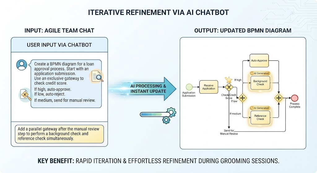
While the logic of BPMN is standardized, the implementation requires a robust tool. Visual Paradigm Online offers a seamless environment for creating these diagrams. By utilizing the AI-assisted features available in the tool, users can input plain-language descriptions of a process and automatically generate a structured BPMN model. This accelerates the transition from “Idea” to “Structured Visual Workflow,” ensuring that the diagram accurately reflects the intended business logic.