


In the realm of system architecture and software engineering, visualizing the lifecycle of a process is crucial. Whether you are a developer mapping out a user authentication flow or a system architect defining state transitions, clarity is key. Visual Paradigm’s VPasCode editor offers a powerful, code-first approach to creating these diagrams, leveraging the PlantUML syntax to generate dynamic State Transition Diagrams (STD) instantly.
This tutorial will guide you through the fundamental concepts of state modeling using the VPasCode environment, breaking down the syntax rules that turn text into visual logic.
What is a State Transition Diagram?
A State Transition Diagram is a behavioral model that describes the different states of a system and the events that cause transitions from one state to another. It answers questions like: “What happens after the user logs in?” or “How does the system handle an invalid request?”
Unlike flowcharts which focus on the flow of control, state diagrams focus on the state of an object. In VPasCode, we represent these states as nodes connected by directed arrows, creating a clear map of system behavior.
Core Syntax Rules for VPasCode
VPasCode simplifies the complexity of drawing diagrams by removing the need for manual placement and alignment. You simply write the code, and the engine renders the visual representation. Here are the essential keywords you need to know to get started.
1. Defining the Flow: Start and Stop
Every process needs an entry point and a logical conclusion. In VPasCode, these are defined by specific keywords that the rendering engine recognizes as the boundaries of your diagram.
start: This keyword defines the initial node. It represents the entry point where the process begins. Visually, this is often rendered as a solid black circle.stop: This keyword marks the termination of a flow. It indicates that the process has ended successfully or been terminated.
2. Modeling Actions
Between the start and stop points, your system performs work. In the syntax, actions are represented by a colon followed by a description.
:Action Name: This defines a specific action or state. Actions are executed sequentially unless otherwise specified. They are implicitly connected, meaning the output of one action flows directly into the next.
3. Control Structures
Real-world systems are rarely linear. They branch based on conditions and repeat processes. VPasCode supports standard programming logic structures:
if (...) then (...) endif: This structure allows you to branch your logic based on a condition. It models decision points where the path changes depending on the outcome.repeat/repeat while: These keywords model repetition loops, allowing you to define processes that run multiple times.fork/fork again/end fork: These are used to model parallel work, where multiple actions happen simultaneously.
Building Your First Diagram: A Practical Example
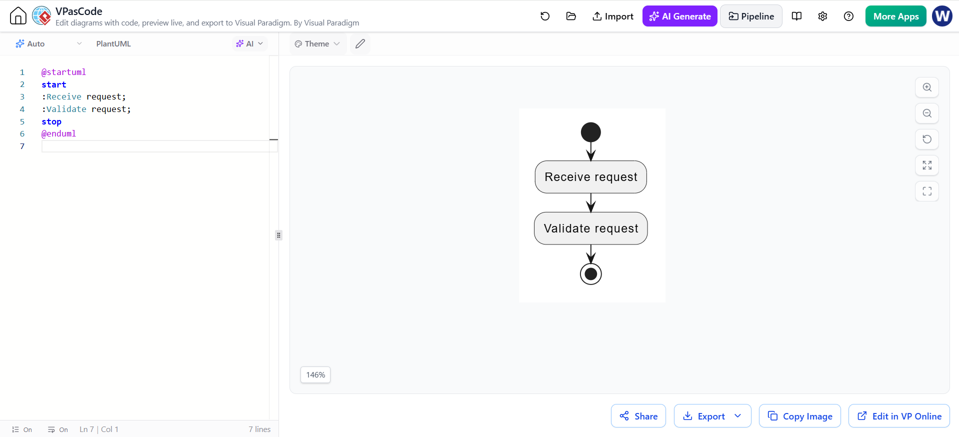
Let’s walk through the minimal example shown in the editor interface. This example models a simple request handling process: receiving a request, validating it, and then stopping.
To visualize this, you would write the following code in the VPasCode editor:
@startuml
start
:Receive request;
:Validate request;
stop
@enduml
Here is a breakdown of how the engine processes this code:
@startuml</code>: This is the directive that tells the engine you are writing PlantUML code. It marks the beginning of the diagram definition.</li>
    <li><code>start</code>: The engine renders a black circle at the top, indicating the process entry.</li>
    <li><code>:Receive request;</code>: The engine creates a node labeled "Receive request" and draws an arrow connecting it to the <code>start</code> node.</li>
    <li><code>:Validate request;</code>: A second node is created for "Validate request," connected by an arrow from the previous action.</li>
    <li><code>stop</code>: A termination node is rendered at the bottom, connected to the validation action.</li>
    <li><code>@enduml
Advanced Features: Labels and Partitions
As your diagrams grow, you will need more control over the layout and information density. VPasCode allows you to add labels to branches to explain why a specific path was taken. Additionally, you can use the partition keyword to group work by responsibility or role, creating swimlanes or distinct sections within your diagram to clarify ownership.
Conclusion
Using VPasCode to create State Transition Diagrams bridges the gap between text-based documentation and visual engineering. By mastering keywords like start, stop, and if, you can rapidly prototype complex system behaviors without getting bogged down in the mechanics of drawing shapes and connecting lines.