


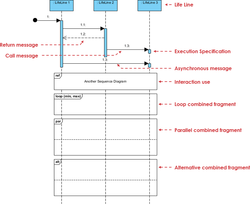
In the world of software engineering, visualizing how different components of a system interact is just as critical as the code itself. UML (Unified Modeling Language) Sequence Diagrams are the industry standard for capturing these dynamic interactions over time. They allow architects and developers to map out the lifecycle of a request from initiation to termination.
This tutorial dissects a classic Online Bookstore Order Checkout scenario. We will break down the architecture, the flow of logic, and the specific UML elements—such as combined fragments and execution specifications—that make this diagram effective.
1. The Participants: LifeLines
Every sequence diagram begins with the participants involved in the interaction. In a UML diagram, these are represented vertically as LifeLines. Think of a LifeLine as a thread of execution or a physical server waiting for a message.
In our Online Bookstore scenario, we have three critical participants:
- LifeLine 1: The Checkout UI / Client Application
This is the entry point. It is the interface the user sees and interacts with. Its primary role is to initiate the request and display the final result.
- LifeLine 2: The Order Service
This is the brain of the operation. It handles the core business logic, including cart processing, inventory validation, and coordinating with other services.
- LifeLine 3: The Payment Gateway
This represents an external system or a secure module responsible for processing financial transactions.
2. The Flow of Execution
Time flows downwards in a sequence diagram. The interactions between LifeLines are depicted as horizontal arrows. Let’s trace the workflow described in the scenario.
Initiation & The Call Message
The process starts when the user submits their order. This triggers a Call Message (a solid line with a filled arrowhead) from the Checkout UI to the Order Service. This message represents a synchronous request, meaning the UI is “waiting” for the Order Service to respond.
Execution Specifications
Upon receiving the request, the Order Service becomes active. In the diagram, this is visualized as a thin, vertical blue rectangle on the LifeLine, known as an Execution Specification (or activation bar). This bar indicates the period during which the component is actively performing an operation.
Asynchronous Messages & Returns
Not all interactions are synchronous. For example, the diagram notes an Asynchronous Message sent to the Payment Gateway. This is drawn as a solid line with an open arrowhead, indicating that the sender does not wait for a response before continuing its own processing. Finally, a Return Message (a dashed line with an open arrow) travels back from the Order Service to the UI, signaling the completion of the transaction.
3. Advanced Modeling: Combined Fragments
Real-world systems are rarely linear. They involve loops, parallel processing, and conditional logic. UML uses Combined Fragments (frames with specific keywords) to model these complex behaviors.
Loop Fragments: Inventory Validation
Before an order can be processed, the system must ensure the books are in stock. The scenario describes a Loop Fragment (labeled loop (min, max)).
This logic dictates that the Order Service iterates through the shopping cart. For every single item, it validates against the inventory database. The loop continues until the minimum and maximum constraints are met, ensuring no item is sold if it is out of stock.
Parallel Processing: Reservation & Fulfillment
Efficiency is key in modern architectures. Once validation is complete, the system enters a Parallel Fragment (labeled par). This allows the system to execute multiple tasks simultaneously without blocking the main thread.
In this scenario, the system performs two tasks at once:
- Reserve the inventory items.
- Notify the warehouse fulfillment service.
Alternative Branching: Payment Logic
Financial transactions are unpredictable. We must handle both success and failure scenarios. This is modeled using an Alternative Fragment (labeled alt).
- Success Path: If the Payment Gateway successfully charges the card, an order confirmation is generated.
- Failure Path: If the payment fails or times out, the system must trigger a rollback. It cancels the inventory reservation and prompts the user to update their payment details.
Modular References: Authentication
To keep diagrams clean and manageable, we sometimes need to reference a separate, more detailed diagram. This is achieved using an Interaction Use (labeled ref).
Throughout the checkout flow, the system references a separate login sequence diagram to handle user authentication and session verification. This modular approach prevents the main diagram from becoming cluttered with low-level authentication details.
4. Tooling for Success
Creating professional-grade UML diagrams requires the right tools. Visual Paradigm is a leading solution for software architects and developers looking to design complex systems.
Visual Paradigm offers a robust, free version that supports the creation of standard UML sequence diagrams. It allows users to:
- Drag and drop LifeLines and messages.
- Automatically generate Combined Fragments (Loop, Alt, Par).
- Export diagrams to various formats for documentation.
By leveraging Visual Paradigm, you can ensure your diagrams are not only technically accurate but also visually consistent and easy to read.
Conclusion
Understanding the Online Bookstore Order Checkout scenario provides a solid foundation for mastering UML Sequence Diagrams. By mastering the interplay between LifeLines, Execution Specifications, and Combined Fragments, you can effectively communicate complex system architectures to your team. Whether you are validating inventory or processing payments, a well-drawn diagram is the blueprint for success.