


Sequence diagrams are the backbone of understanding how software systems interact over time. Whether you are designing a microservice architecture or mapping out a user authentication flow, visualizing the chronological exchange of data is crucial. In the world of diagramming tools like VPasCode and PlantUML, syntax precision dictates how clearly your system’s logic is communicated.
This tutorial breaks down the syntax of message arrows, the flow of time, and the specific conventions used to distinguish between a request and a response.
The Anatomy of a Message
In a UML sequence diagram, every interaction is a line of code that translates into a visual arrow. The structure of these messages follows a strict formula to ensure readability across all diagramming tools.
The Syntax Formula
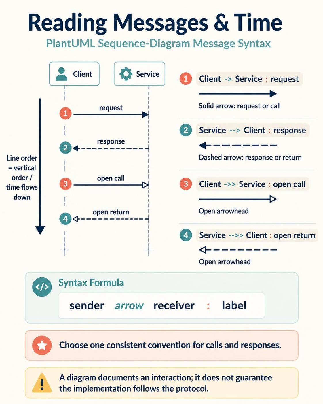
Every message line consists of three distinct parts: the origin, the connector, and the destination, followed by a description of the action.
sender arrow receiver : label- Sender: The participant initiating the interaction (e.g.,
Client). - Arrow: The connector type defining the nature of the interaction (e.g.,
->,-->). - Receiver: The participant receiving the interaction (e.g.,
Service). - Label: The text description of the message payload or action.
Visualizing Time and Order
One of the most fundamental concepts in sequence diagrams is the vertical axis. Unlike flowcharts that may flow in any direction, sequence diagrams are strictly chronological.
As illustrated in the diagram, the vertical order of the lines directly determines the timeline. Time flows downwards. If you write a “response” line before the “request” line in your code, the diagram will render incorrectly, implying the response happened before the request. To fix this, simply reorder the lines in your text editor.
Decoding Arrow Styles
The arrow style you choose is not just an aesthetic preference; it carries semantic meaning regarding the type of communication occurring between participants.
1. Solid Arrows: The Request
When you need to represent a call, a request, or a synchronous command, you use a solid line with a filled arrowhead.
Client -> Service : requestThis indicates that the Client is actively doing something to the Service. It is the primary driver of the interaction.
2. Dashed Arrows: The Response
Responses, returns, or asynchronous notifications are typically represented by dashed lines. This visual distinction immediately separates the “action” from the “reaction.”
Service --> Client : responseThis tells the reader that the Service is replying to the previous request. In many tools, this is the standard for return values.
3. Open Arrowheads
Sometimes, standard arrows look cluttered, or you want to emphasize a specific style. PlantUML supports open arrowheads for a cleaner, more modern look.
- Open Call:
->>creates a solid line with an open arrowhead. - Open Return:
-->>creates a dashed line with an open arrowhead.
Client ->> Service : open call
Service -->> Client : open return
Consistency and Protocol
While the syntax allows for flexibility, the diagram includes a critical warning regarding implementation.
Choose a consistent convention for calls and responses.
Do not mix
->for calls in one section and-->for calls in another. If you define solid arrows as “requests” in the legend, ensure you use them consistently throughout the diagram.
Furthermore, remember that a diagram is a specification, not a guarantee. As noted in the source material: “UML diagrams communicate an interaction; they do not automatically guarantee that the implementation follows the depicted protocol.” The diagram is a contract between the developer and the system design.