


In the world of software engineering, visualizing the dynamic behavior of a system is just as critical as defining its static structure. UML Sequence Diagrams are the industry standard for illustrating how objects interact over time to achieve a specific goal. Whether you are designing a database query handler or orchestrating complex microservices, understanding the flow of messages is essential.
This tutorial will guide you through the architecture of a classic database interaction pattern using Visual Paradigm, the leading UML modeling tool. We will analyze the lifecycle of a database query, breaking down the message flow, object creation, and resource management involved in a robust system design.
Understanding the Core Components
Before we delve into the logic of the diagram, let us identify the fundamental building blocks presented in this sequence.
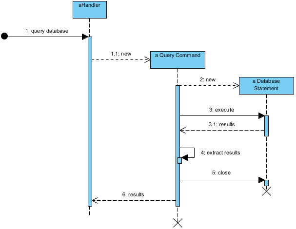
- Actors and Participants: The diagram begins with
aHandler, an object responsible for processing the initial request. It acts as the entry point for the system logic. - Creation of Commands: The system does not execute queries immediately. Instead, it creates a
a Query Commandobject. This follows the Command Pattern, allowing queries to be encapsulated as objects. - Execution Context: The command delegates the actual work to a
a Database Statement. This represents a prepared SQL statement or a database cursor. - Activation Bars: The vertical blue rectangles on the lifelines represent the period during which an object is performing an action or is active.
- Return Messages: Dashed arrows (like 1.1: new and 3.1: results) indicate the return of control or data from the called object back to the caller.
Step-by-Step Interaction Analysis
Let us walk through the sequence of events depicted in the diagram, understanding the logic behind every arrow.
1. The Initial Trigger and Query Construction
The sequence starts with an external trigger, represented by the black circle, sending a message to aHandler. The message is labeled 1: query database. This initiates the flow. The handler does not execute the query directly; instead, it delegates the responsibility to create a command object.
The message 1.1: new indicates that aHandler instantiates a a Query Command object. Notice the dashed arrow with an open arrowhead, which is the standard UML notation for object creation.
2. Instantiating the Database Statement
Once the query command exists, it must prepare the specific instructions for the database. The command object sends a message 2: new to instantiate a a Database Statement. This is a crucial step in performance optimization; it separates the creation of the query logic from the execution.
3. Execution and Data Retrieval
With the statement prepared, the a Query Command sends the 3: execute message. This causes the activation bar on the a Database Statement to appear, signifying that the database connection is busy processing the request.
Once the database processes the request, it returns the data via the dashed arrow 3.1: results. The control returns to the a Query Command, which is now active to process this data.
4. Processing and Resource Cleanup
The command object performs an internal operation, labeled 4: extract results. This self-referential message indicates that the object is manipulating the returned data (e.g., parsing JSON, converting to a DTO, or filtering rows).
Finally, the diagram emphasizes resource management. The command sends a 5: close message to the a Database Statement. This is vital to prevent memory leaks and ensure database connections are returned to the pool. The lifecycle ends with an ‘X’ on the lifeline, symbolizing the destruction of the object.
5. Returning the Final Outcome
After successfully extracting the results and closing the database connection, the a Query Command returns the final payload to the original handler via message 6: results. The handler can now proceed with the next steps of the business logic.
Why Use Visual Paradigm for This?
Creating complex sequence diagrams manually is prone to errors. Using Visual Paradigm allows you to:
- Drag-and-Drop Modeling: Easily add participants and messages without worrying about alignment.
- Auto-layout: The tool automatically adjusts the vertical positioning of messages to maintain a clean flow.
- Code Generation: You can generate actual Java, C#, or Python code directly from this diagram, ensuring your implementation matches your design.
Conclusion
By breaking down the interaction between aHandler, a Query Command, and a Database Statement, we have uncovered a robust architectural pattern. This sequence diagram not only documents the code but also serves as a blueprint for developers to understand the lifecycle of data processing. Using Visual Paradigm, you can transform these abstract concepts into concrete, executable designs.