


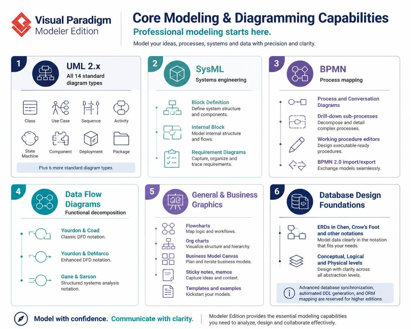
In the realm of software engineering and systems analysis, clarity is currency. The Visual Paradigm Modeler Edition represents the foundational layer for professional modeling, offering a robust toolkit designed to bridge the gap between abstract ideas and concrete technical specifications. This tutorial explores how to leverage the core modeling capabilities found in this edition to architect complex systems, define business processes, and design data structures.
1. The Backbone of Software Design: UML 2.x
Unified Modeling Language (UML) remains the gold standard for visualizing, specifying, constructing, and documenting the artifacts of software systems. The Modeler Edition provides complete support for all 14 standard UML diagram types, allowing you to approach system design from multiple perspectives.
Structural vs. Behavioral Diagrams
To effectively model a system, you must distinguish between what the system is (Structure) and what the system does (Behavior).
- Class Diagrams: The cornerstone of Object-Oriented design, illustrating static structure, attributes, operations, and relationships between classes.
- Use Case Diagrams: Essential for capturing functional requirements from the perspective of external actors interacting with the system.
- Sequence Diagrams: Critical for modeling the dynamic interactions and message flow between objects over time.
- State Machine Diagrams: Used to model the lifecycle of a specific object, detailing its states and the transitions triggered by events.
2. Engineering Complex Systems with SysML
While UML is excellent for software, SysML (Systems Modeling Language) is a general-purpose language designed to address the needs of multidisciplinary systems engineering. It is a profile of UML 2.x, meaning it reuses UML concepts but extends them to cover the entire system lifecycle.
The Four Key Diagram Types
- Block Definition Diagrams (BDD): The foundation of SysML. These diagrams define the structure of the system, including the system itself, its parts, and the relationships between them (e.g., composition or aggregation).
- Internal Block Diagrams (IBD): These drill down into the “black box” of a Block to show the internal structure, specifically the ports and connectors that define how parts exchange information.
- Requirement Diagrams: These allow engineers to capture, organize, and trace requirements. You can link specific requirements to the system blocks that satisfy them, ensuring full traceability from concept to implementation.
3. Mapping Business Logic with BPMN
Business Process Model and Notation (BPMN) bridges the gap between business process management and technical implementation. The Modeler Edition supports advanced BPMN features, including Process Diagrams and Conversation Diagrams.
Decomposing Complexity
One of the most powerful features for process modeling is the ability to use drill-down sub-processes. This allows you to create a high-level overview of a workflow and then “drill down” into a specific task to reveal its detailed internal logic without cluttering the main diagram.
graph TD
    Start((Start)) --> Task1[Process Order]
    Task1 --> Task2{Is Payment Valid?}
    Task2 -- Yes --> Task3[Ship Item]
    Task2 -- No --> Task4[Notify Customer]
    Task3 --> End((End))
    Task4 --> End
4. Functional Decomposition: Data Flow Diagrams (DFD)
For systems analysts focusing on functional decomposition rather than object-oriented structure, Data Flow Diagrams are indispensable. The Modeler Edition supports three distinct styles of DFD notation, catering to different analytical preferences:
- Yourdon & Coad: Uses circles for processes and open-ended rectangles for data stores. This is often preferred for its clean, distinct look.
- Yourdon & DeMarco: A variation that uses squares for processes, maintaining the same data store symbol.
- Gane & Sarson: Widely used in structured systems analysis. It uses rounded rectangles for processes and specific symbols for data stores, often providing a more “flowchart-like” appearance.
5. Database Design Foundations
Effective software relies on robust data architecture. The Modeler Edition supports Entity Relationship Diagrams (ERDs) at all levels of abstraction:
- Conceptual Level: Focuses on high-level entities and relationships without worrying about specific data types or keys.
- Logical Level: Adds attributes and defines primary/foreign keys, refining the model for specific business rules.
- Physical Level: Maps the design to a specific database management system (DBMS), incorporating data types and constraints.
Note: While the Modeler Edition allows you to design these diagrams using Chen or Crow’s Foot notations, advanced features like automated DDL generation and ORM mapping are reserved for the higher-tier Developer Edition.
Conclusion
By mastering these core capabilities—from the structural rigor of UML and SysML to the process clarity of BPMN and DFD—you can “Model with confidence and Communicate with clarity.” Whether you are defining the architecture of a distributed system or mapping a complex business workflow, the Modeler Edition provides the essential foundation for success.