


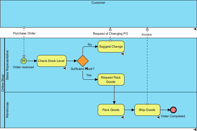
In the rapidly evolving landscape of business operations, companies often face the challenge of scaling their infrastructure without disrupting service. This tutorial explores how to transition from a basic “As-Is” process to a robust “To-Be” process model using Visual Paradigm. We will specifically focus on a scenario where a business has expanded to include a dedicated warehouse, necessitating a new workflow for inventory management, packing, and shipping.
By leveraging BPMN (Business Process Model and Notation) swimlanes, we can visualize the complex interactions between the Sales Representative, the Warehouse team, and the Customer. This guide will walk you through the architectural decisions and modeling steps required to create this optimized process diagram.
Conceptualizing the To-Be Architecture
Before opening Visual Paradigm, it is essential to understand the logic of the new system. The “To-Be” process is not merely a drawing; it is a representation of future efficiency. In our scenario, the business has grown, and stock is no longer managed informally. We must now account for:
- Inventory Validation: The Sales Representative must verify if items are in stock before confirming an order.
- Decision Logic: If stock is insufficient, the process must divert to a modification path rather than failing.
- Physical Fulfillment: A new “Warehouse” role is introduced to handle the physical packing and shipping of goods.
Step-by-Step Modeling in Visual Paradigm
Visual Paradigm provides a comprehensive suite of BPMN tools. To build this process, we will use the Swimlane diagram structure to separate responsibilities clearly.
1. Setting Up the Swimlanes
First, create a new BPMN diagram in Visual Paradigm. You will need to define three distinct swimlanes to represent the flow of information and physical goods:
- Customer: The external entity initiating the request and receiving the final product.
- Online Shop (Sales): The internal department handling communication and inventory checks.
- Warehouse: The new operational unit responsible for physical logistics.
2. The Order Initiation and Inventory Check
The process begins when the Customer submits a Purchase Order. In the “Online Shop” lane, the Sales Representative receives this order. The first critical control point is the “Check Stock Level” activity.
In Visual Paradigm, drag a “Task” element and name it Check Stock Level. Connect the incoming “Order received” event to this task. This represents the transition from receiving the request to validating it.
3. Implementing Decision Logic (Gateways)
Business processes are rarely linear. They require decision points. After checking the stock, the system must answer a specific question: “Is there sufficient stock?”
To model this:
- Add a Exclusive Gateway (Diamond shape) to the diagram.
- Connect the “Check Stock Level” task to this gateway.
- Create two outgoing flows labeled Yes and No.
4. Handling the “No” Path: Suggesting Changes
If the answer to the stock check is “No”, the process cannot proceed to packing. Instead, it must notify the customer. This is modeled as a “Suggest Change” task.
Connect the No flow from the gateway to a new Task named Suggest Change. From here, you can model a message flow back to the Customer (often represented by a dashed line with an envelope icon) to request a revised Purchase Order, effectively closing the loop on the failed transaction.
5. The “Yes” Path: Warehouse Operations
If the stock is sufficient, the flow continues. This is where the integration between the “Online Shop” and the “Warehouse” becomes visible.
- Connect the Yes flow to a task named
Request Pack Goods. - Transition the process flow into the Warehouse swimlane.
- Add a task named
Pack Goods. - Follow this with
Ship Goods.
The completion of the shipping process is marked by an End Event (a thick circle), signifying “Order Completed”.
flowchart TD
    subgraph Customer
        Cust[Customer]
    end

    subgraph Online_Shop
        Sales[Sales Representative]
        CheckStock[Task: Check Stock Level]
        Gateway((Gateway))
        SuggestChange[Task: Suggest Change]
    end

    subgraph Warehouse
        RequestPack[Task: Request Pack Goods]
        PackGoods[Task: Pack Goods]
        ShipGoods[Task: Ship Goods]
        EndEvent[End Event: Order Completed]
    end

    Cust -- Order Received --> Sales
    Sales --> CheckStock
    CheckStock --> Gateway
    Gateway -- No --> SuggestChange
    SuggestChange -- Request Change --> Cust
    Gateway -- Yes --> RequestPack
    RequestPack --> PackGoods
    PackGoods --> ShipGoods
    ShipGoods --> EndEvent
Refining the Model
Once the basic flow is established, review the diagram for clarity. Ensure that the transition between the “Online Shop” and “Warehouse” is logical. In our model, the “Request Pack Goods” task acts as the handover point. While it resides in the Sales lane in some models, it often triggers the action in the Warehouse lane. Ensure your Visual Paradigm configuration correctly handles the interaction between these lanes.
Conclusion
By following these steps, we have successfully modeled a “To-Be” process that accommodates a new warehouse. This diagram serves as a blueprint for implementation, allowing stakeholders to visualize bottlenecks, such as the decision point at the stock check, and understand how the new resources will be allocated. Visual Paradigm’s intuitive interface makes translating these business requirements into technical diagrams seamless.