


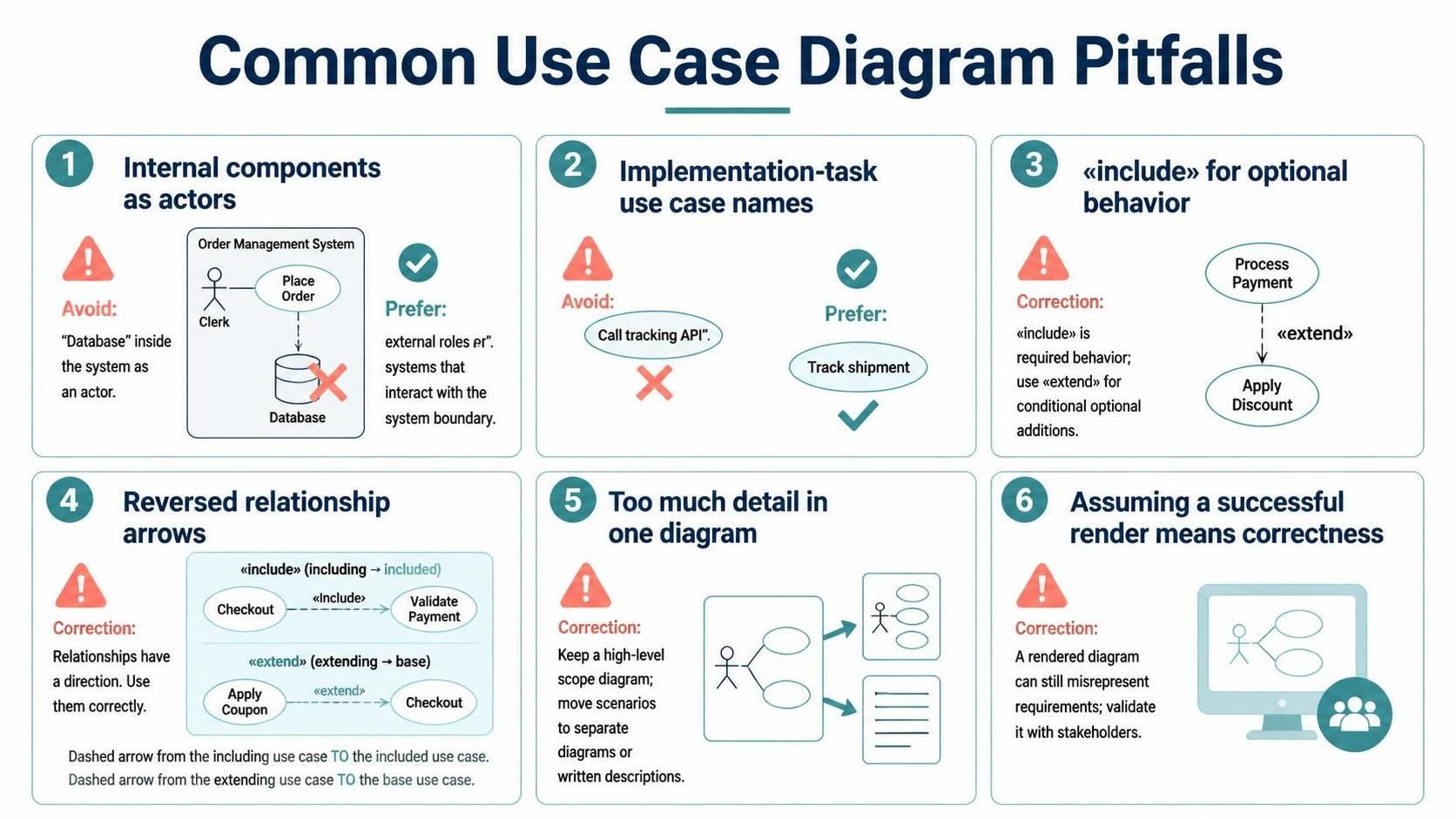
Creating a Use Case Diagram is often the first step in defining the functional requirements of a software system. It serves as a contract between the development team and the stakeholders, outlining what the system does from the perspective of its users. However, even experienced architects can fall into traps that result in diagrams that look correct but are semantically wrong.
In this tutorial, we will deconstruct six common pitfalls found in UML modeling, specifically tailored for users of the Visual Paradigm AI Assisted VPasCode Editor. By understanding these errors, you can ensure your diagrams accurately represent your system’s architecture and requirements.
1. Modeling Internal Components as Actors
One of the most frequent mistakes is confusing the internal architecture of the system with the external world. Actors represent roles played by external entities—people, organizations, or other systems—that interact with your system from the outside.
If you draw a stick figure labeled “Database” or “File System” inside your system boundary, you are misrepresenting the interaction. The database is part of the system’s implementation, not an external role.
The Rule: Actors must be external to the system boundary. Internal components like databases, caches, or legacy systems should be modeled as sub-systems or part of the system itself, not as actors.
@startuml
left to right direction
actor "Clerk" as Clerk
rectangle "Order Management System" {
  usecase "Place Order" as UC1
  database "Database" as DB
  UC1 --> DB
  Clerk --> UC1
}
@enduml
2. Naming Use Cases as Implementation Tasks
Use cases describe what the system does to provide value, not how it does it. A common error is naming a use case after a specific API call or database transaction.
Consider the difference between “Call Tracking API” and “Track Shipment.” The former is an implementation detail that might change if you switch cloud providers. The latter is a functional goal that remains constant. Your diagrams should remain stable despite changes in technology.
- Bad: “Call Tracking API,” “Update Database,” “Send Email.”
- Good: “Track Shipment,” “Update Order Status,” “Notify Customer.”
3. Misusing the «include» Relationship
Many modelers incorrectly use the «include» relationship for optional behaviors or alternative paths. In UML, the «include» relationship represents behavior that is required for the base use case to complete.
If a step is optional or conditional, you should use the «extend» relationship. «Include» is for extracting common behavior (like “Validate User” for both “Login” and “Reset Password”), while «Extend» is for adding optional features (like “Apply Discount” to “Checkout”).
@startuml
usecase "Process Payment" as Payment
usecase "Apply Discount" as Discount

' Correct: Discount is optional
Payment ..> Discount : <>
@enduml
4. Reversing Relationship Arrows
UML relationships are directional. Reversing the arrow changes the semantic meaning of the diagram, often leading to logic errors in the generated code or the understanding of the requirements.
The direction of the arrow indicates the flow of control or dependency:
- «include»: The arrow points from the including use case TO the included use case. The base case needs the included case to run.
- «extend»: The arrow points from the extending use case TO the base use case. The extension adds behavior to the base case.
5. Crowding One Diagram with Details
A common tendency is to try to capture every single scenario and detail in a single “Master Diagram.” This leads to a “spaghetti diagram” that is impossible to read or maintain.
The Strategy: Start with a high-level scope diagram that shows the major actors and primary use cases. Then, break down complex use cases into separate diagrams or detailed textual descriptions. Visual Paradigm allows you to manage this complexity by creating multiple diagrams linked together.
6. Assuming a Successful Render Means Correctness
Just because Visual Paradigm successfully renders a diagram does not mean the model is logically sound. The tool is syntactically strict, but it cannot validate your business logic.
You might have a perfectly rendered diagram where the logic is backwards (e.g., a user “includes” the system). Always validate your model against your requirements documentation and stakeholder interviews. A diagram that compiles is not necessarily a diagram that works.