


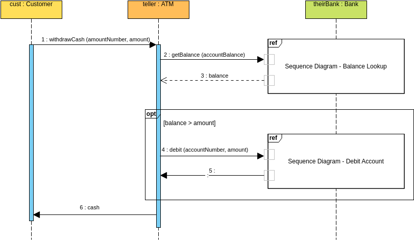
Designing robust financial systems requires more than just backend logic; it demands a clear visualization of how different entities interact over time. In this tutorial, we will dissect a classic Sequence Diagram representing an Automated Teller Machine (ATM) cash withdrawal process. This guide serves as a comprehensive walkthrough for software architects and developers looking to model complex system behaviors using Visual Paradigm.
By breaking down the interaction between the Customer, the ATM Teller, and the Bank Server, we will explore how to structure logic flows, handle conditional branching, and utilize reference fragments to manage complexity.
Understanding the Actors and Lifelines
In any sequence diagram, the first step is defining the participants. These are represented by Lifelines—the vertical dashed lines extending from the top of the diagram. In this specific scenario, we have three distinct roles:
- cust : Customer: The initiator of the transaction. This actor represents the human user interacting with the interface.
- teller : ATM: The intermediary system. In this context, the ATM acts as the “teller,” processing requests and managing the physical interface.
- theirBank : Bank: The backend service responsible for verifying funds and executing the financial ledger update.
Notice the activation bars (the blue rectangles) on the lifelines. These indicate periods during which an object is performing an action or waiting for a response. The depth and width of these bars help visualize the concurrency and duration of operations within the system.
Step-by-Step Interaction Analysis
Let’s trace the flow of messages, which are the horizontal arrows connecting the lifelines. These represent method calls or data exchanges.
1. The Initiation
The process begins when the customer requests cash. This is a synchronous message sent from the cust lifeline to the teller lifeline:
1 : withdrawCash (amountNumber, amount)
Here, the ATM receives the account number and the withdrawal amount. The activation bar on the ATM lifeline begins immediately, indicating it is now “busy” processing this request.
2. Balance Verification (The Reference Fragment)
Before dispensing cash, the ATM must verify that sufficient funds exist. Instead of cluttering the diagram with the entire logic of a balance check, the model uses a Reference Fragment (ref). This is a best practice for managing complexity in large systems.
2 : getBalance (accountBalance)
   [ref] Sequence Diagram - Balance Lookup
Message 2 requests the balance. The dashed arrow labeled “3 : balance” represents the return value from the Bank. This interaction is encapsulated in a box labeled Sequence Diagram – Balance Lookup, implying that the detailed logic exists in a separate, linked diagram.
3. Conditional Logic (The Opt Fragment)
Financial transactions almost always involve decision-making. In this diagram, the logic is wrapped in an Opt (Optimization/Optional) fragment. This block is executed only if a specific condition is met.
[opt]
    [balance > amount]
The condition [balance > amount] is the guard clause. If the customer’s balance is greater than the requested amount, the system proceeds to debit the account. If the condition is false, the entire block is skipped, and the transaction is likely denied (though the denial path is not explicitly drawn in this snippet).
4. The Debit Operation
Inside the opt block, the ATM sends a debit request to the Bank:
4 : debit (accountNumber, amount)
   [ref] Sequence Diagram - Debit Account
Similar to the balance check, the actual debit logic is abstracted away into a Reference Fragment. This keeps the main high-level diagram clean while allowing developers to drill down into the specific implementation of the Debit Account process elsewhere.
Tooling: Visual Paradigm
To achieve this level of modeling precision, we utilize Visual Paradigm, a powerful Unified Modeling Language (UML) tool. Visual Paradigm offers a robust environment for creating sequence diagrams that go beyond simple drawing.
When using Visual Paradigm, the following features are essential for the diagram presented above:
- Fragment Management: The tool allows you to easily insert “Alt” (Alternative), “Opt” (Optional), and “Ref” (Reference) fragments. You can click a button, select the type, and the tool automatically generates the correct frame syntax.
- Message Labeling: Visual Paradigm handles synchronous (solid arrow) and asynchronous (dashed arrow) messages intuitively. You can double-click a message to edit parameters like
(amountNumber, amount). - Collaboration Diagrams: You can link the “Reference” boxes to other diagrams within the same project, creating a seamless hyperlinked documentation system.
Using Visual Paradigm ensures that your diagrams are not just static images, but part of a living, integrated system model that can be validated against your code.
Conclusion
By utilizing the sequence diagram, we have successfully modeled a secure and logical flow for an ATM transaction. The combination of clear lifelines, conditional opt blocks, and abstracted ref fragments demonstrates how to handle complex logic without overwhelming the reader.
Whether you are documenting existing systems or designing new ones, mastering these interaction patterns is crucial for building maintainable and scalable software architectures.