


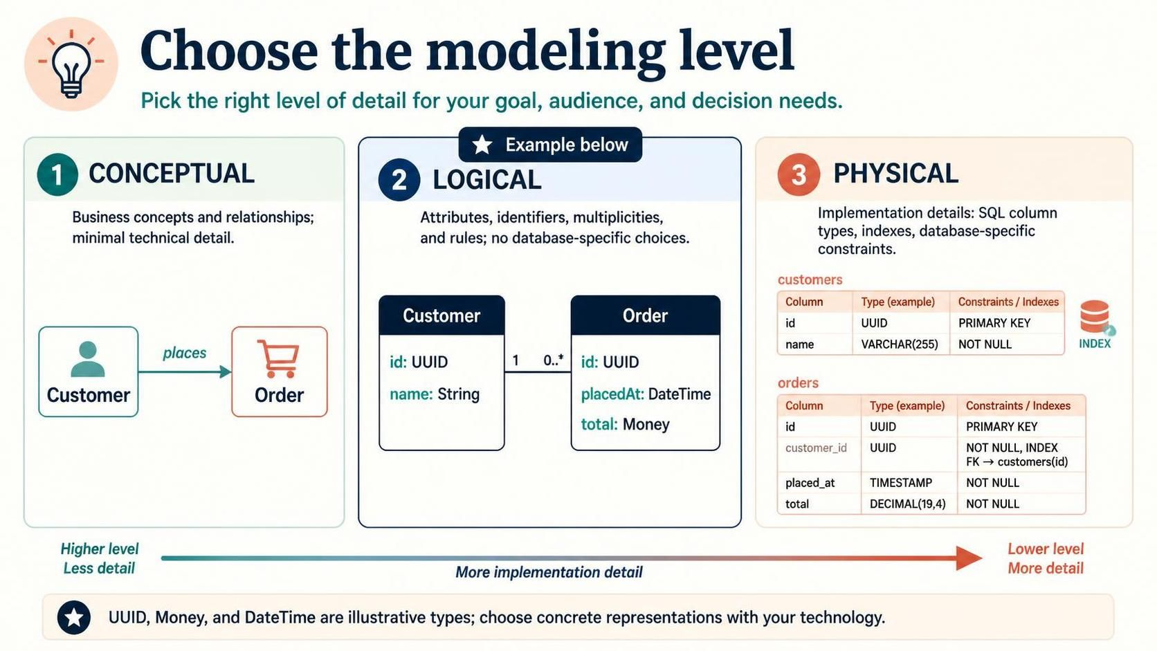
When designing complex software systems, the gap between a business idea and a functioning database can feel insurmountable. The secret to bridging this gap is not to rush to the database, but to climb the ladder of abstraction step-by-step. As shown in the “Choose the modeling level” diagram, effective data modeling requires distinct phases: Conceptual, Logical, and Physical. Each phase serves a specific audience and purpose, and conflating them often leads to rigid, unchangeable systems.
In this tutorial, we will explore these three modeling levels using a classic Customer and Order domain. We will also see how to implement the middle step—the Logical Model—using the VPasCode editor within Visual Paradigm UML.
Level 1: The Conceptual Model (The “What”)
The Conceptual model is the conversation starter. It is designed for business stakeholders, product managers, and architects. At this stage, technical details like data types, primary keys, or SQL syntax are irrelevant distractions.
- Focus: Business concepts, domain entities, and high-level relationships.
- Key Feature: Minimal technical detail. For example, a relationship is simply “places” rather than a foreign key constraint.
- Example: A simple diagram showing a Customer icon connected to an Order icon via an arrow labeled “places”.
The goal here is to validate the business logic. Does a Customer place an Order? Yes. Is that the right mental model for the business? If not, you fix it here, before writing a single line of code.
Level 2: The Logical Model (The “How” – Abstract)
Once the concepts are agreed upon, we move to the Logical Data Model (LDM). This is where the structure is defined without being tied to a specific database technology (like PostgreSQL vs. Oracle). It is the blueprint that architects and developers use to understand data requirements.
Key Components of the Logical Model
As illustrated in the center panel of your reference image, the Logical model introduces:
- Attributes: Defining the data inside the entities (e.g.,
name,placedAt). - Identifiers: Defining the Primary Keys (e.g.,
id: UUID). - Multiplicities: Defining the cardinality of relationships (e.g., 1 Customer to 0..* Orders).
- Rules: Constraints that apply to the data, independent of the database engine.
VPasCode Implementation:
To create this in Visual Paradigm using the VPasCode editor, you define the entities and their relationships using a domain-specific language. Below is the code snippet representing the Logical Model shown in your image.
entity Customer {
  id: UUID
  name: String
}

entity Order {
  id: UUID
  placedAt: DateTime
  total: Money
}

Customer "1" -- "0..*" Order : places
In this snippet, we use abstract types like UUID, DateTime, and Money. These are placeholders that represent the logical requirement, not the specific SQL type yet.
Level 3: The Physical Model (The “How” – Concrete)
The Physical Data Model (PDM) is the final blueprint for the database administrators (DBAs) and developers. It translates the abstract logical types into concrete database implementation details.
From Logical to Physical
This is where the magic of “implementation details” happens. The abstract UUID becomes VARCHAR(36) or CHAR(36) depending on the DB engine. The Money type becomes DECIMAL(19,4) to handle precision.
As seen in the third panel of the diagram, the Physical model adds:
- SQL Column Types: Specific data types (e.g.,
TIMESTAMP,VARCHAR(255)). - Constraints:
NOT NULL,UNIQUE, andPRIMARY KEYdeclarations. - Indexes: Optimization strategies like
INDEX(customer_id)to speed up lookups. - Foreign Keys: Explicit linking between tables (e.g.,
FK -> customers(id)).
The diagram shows the orders table linking back to customers via a foreign key. This physical constraint ensures referential integrity at the database level.
Summary: The Modeling Ladder
The progression from left to right in the diagram represents a shift from Higher Level/Less Detail to Lower Level/More Detail.
- Conceptual: “We have Customers and Orders.”
- Logical: “A Customer has a Name and places many Orders with a Total Price.”
- Physical: “The Orders table stores the Total Price as a Decimal and indexes the Customer ID for fast retrieval.”
By separating these concerns, you ensure that your system design is robust, flexible, and aligned with both business needs and technical realities.