


Introduction & System Overview
In the finance industry, clarity is currency. When designing complex banking systems like an Automated Teller Machine (ATM), understanding the interactions between users and the system is critical. A Use Case Diagram provides that high-level view, mapping out actors (such as Customers, Tellers, and Administrators) and their specific capabilities within the system.
For software architects and developers, using a diagram-as-code approach offers significant advantages over traditional drag-and-drop tools. With VPasCode, you can version control your diagrams, collaborate via Git, and generate professional visuals instantly using PlantUML. In this masterclass, we will build a robust ATM System Use Case diagram, demonstrating how to structure actors, system boundaries, and relationships efficiently.
Complete Diagram & Full Source Code
Before diving into the construction steps, here is the complete, finished diagram. You can view the visual output below and inspect the source code immediately following it.
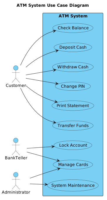
Copy the complete source code below to replicate this diagram in VPasCode or any PlantUML editor.
@startuml
!include https://static.visual-paradigm.com/web/resources/plantuml-stdlib/themes/vp.puml

left to right direction
skinparam packageStyle rectangle

title ATM System Use Case Diagram

actor Customer
actor BankTeller
actor Administrator

rectangle "ATM System" {
  usecase "Withdraw Cash" as UC1
  usecase "Deposit Cash" as UC2
  usecase "Check Balance" as UC3
  usecase "Transfer Funds" as UC4
  usecase "Print Statement" as UC5
  usecase "Change PIN" as UC6
  usecase "Lock Account" as UC7
  usecase "Manage Cards" as UC8
  usecase "System Maintenance" as UC9
}

Customer --> UC1
Customer --> UC2
Customer --> UC3
Customer --> UC4
Customer --> UC5
Customer --> UC6

BankTeller --> UC7
BankTeller --> UC8

Administrator --> UC9
Administrator --> UC8


@endumlStep-by-Step Breakdown & Thought Process
Building a professional diagram from scratch requires a logical flow. Here is how I approached the design of this ATM System Use Case diagram using VPasCode.
1. Setting Up the Foundation
Every PlantUML diagram starts with the @startuml directive. To ensure our diagram looks professional and aligns with modern design standards, I immediately included the VPasCode theme. This ensures consistent styling for actors, use cases, and system boundaries.
@startuml
!include https://static.visual-paradigm.com/web/resources/plantuml-stdlib/themes/vp.puml2. Defining Direction and Style
For use case diagrams, a horizontal layout often reads better than a vertical one. I set the direction to left to right and specified a rectangular style for the system boundary package. This creates a clean container for the system logic.
left to right direction
skinparam packageStyle rectangle
3. Declaring Actors and System Boundary
Next, I defined the title and the external actors interacting with the system. In this finance use case, we have three distinct roles: the Customer (primary user), the BankTeller (support staff), and the Administrator (system maintenance).
I then enclosed the core functionality within a rectangle labeled “ATM System”. This boundary is crucial as it visually separates internal system processes from external entities.
title ATM System Use Case Diagram

actor Customer
actor BankTeller
actor Administrator

rectangle "ATM System" {4. Mapping Use Cases and Relationships
Inside the system boundary, I defined nine distinct use cases, ranging from basic transactions like “Withdraw Cash” to administrative tasks like “System Maintenance”. I assigned unique IDs (UC1-UC9) to each use case. This makes it easier to reference them when drawing relationships.
Finally, I mapped the interactions. The Customer connects to standard banking functions. The BankTeller handles account security and card management. The Administrator oversees maintenance and card management. Using the --> syntax clearly indicates the flow of interaction.
Customer --> UC1
Customer --> UC2
...
BankTeller --> UC7
...
Administrator --> UC9

@endumlKey Takeaways & Best Practices
- Use System Boundaries: Always enclose your use cases in a rectangle or boundary to clearly define the scope of the system being modeled.
- Group Related Actors: Ensure your actors are distinct. In finance, distinguishing between a Customer and an Administrator is vital for security modeling.
- Leverage Themes: Don’t reinvent the wheel. Including the VPasCode theme file ensures your diagram looks polished and consistent with industry standards without manual CSS tweaking.
Try It Yourself with VPasCode
Ready to model your own finance or software architecture diagrams? VPasCode is the free, browser-based PlantUML editor designed for developers who value speed and precision.
Experience the power of diagram-as-code today.
Your attention-grabbing headline here
One short, benefit-driven sentence telling readers exactly what they’ll get.