Bridging the Gap Between Design and Development
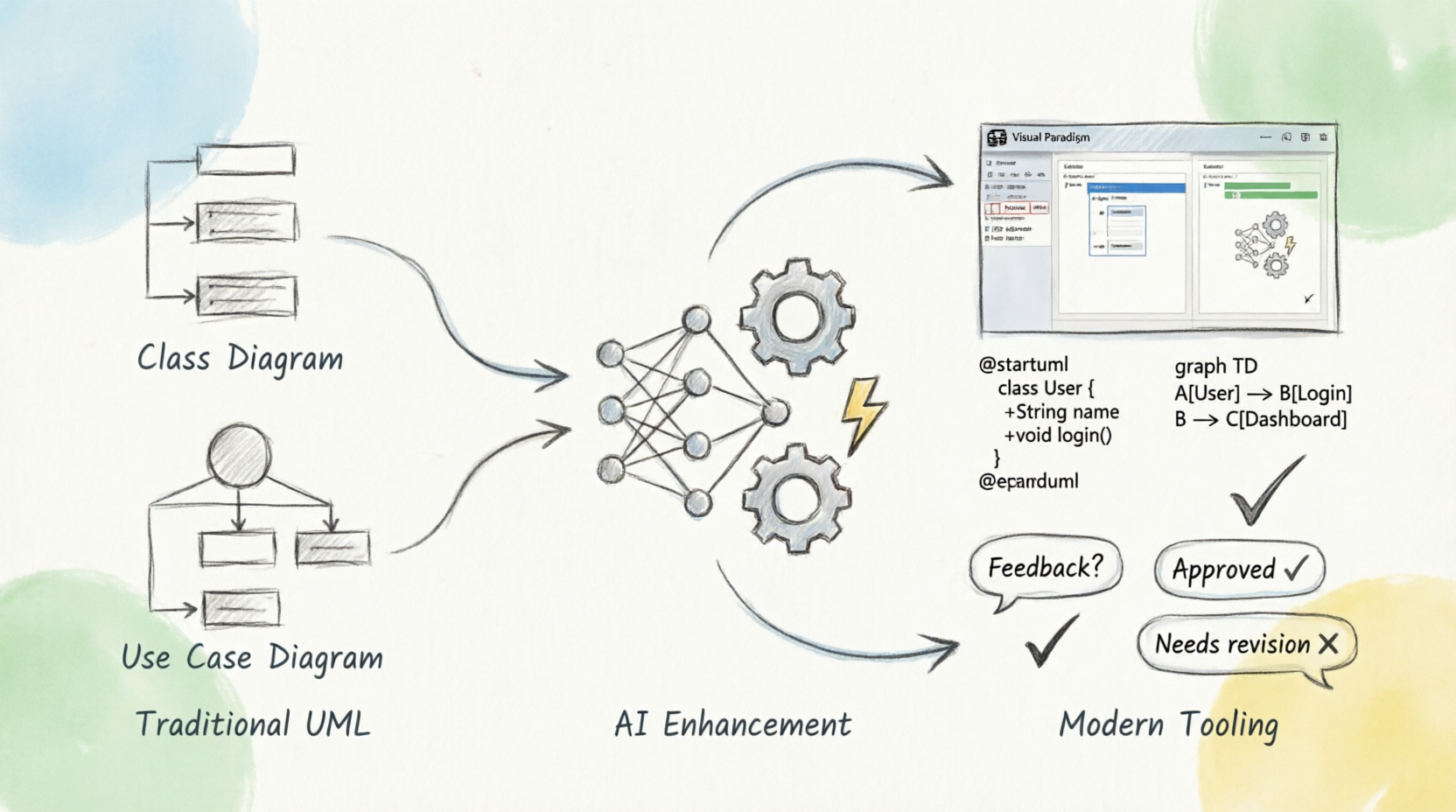
In the world of software architecture, there is often a frustrating disconnect between the visual models we draw on paper (or digital whiteboards) and the actual code that powers our applications. For years, this “implementation gap” required developers to manually transcribe complex Class or Use Case diagrams into programming languages. However, looking at the evolution depicted in the diagram, we can see a much more streamlined path emerging.
The Foundation: Traditional UML
Our journey begins on the left side of the process flow, labeled Traditional UML. Here, we see the raw materials of software design: the Class Diagram and the Use Case Diagram.
- Class Diagrams: These define the structure of your system, outlining objects, their attributes, and relationships.
- Use Case Diagrams: These map out user interactions, showing who does what within the system.
Historically, these were static representations. Once drawn, they existed as images or diagrams that needed to be manually interpreted by a developer to create the underlying logic. While essential for planning, they were not yet executable.
The Catalyst: AI Enhancement
Enter the middle stage: AI Enhancement. This section of the diagram illustrates the transformation engine. Represented by gears turning and a neural network icon, this phase signifies the integration of Artificial Intelligence into the modeling lifecycle.
Instead of a human typing out every line of syntax, the AI acts as an intelligent interpreter. It analyzes the structural data from your Class and Use Case diagrams. The gears symbolize the processing power working behind the scenes to understand context, while the neural network represents the learning algorithms that have been trained to recognize patterns in software design. This is where the magic happens—the shift from passive visuals to active data.
The Result: Modern Tooling and Feedback Loops
The final destination on the right is Modern Tooling, specifically within an environment like Visual Paradigm. This stage demonstrates the output of the AI process. The abstract diagrams are now converted into concrete, editable code formats such as @startuml (PlantUML) and graph definitions.
What makes this workflow powerful is the interface shown in the top right corner. You aren’t just generating code; you are interacting with it. The diagram highlights two critical outcomes:
- Approval: If the generated code matches your architectural vision, you click “Approved.” The model moves forward to implementation.
- Feedback Loop: If the code needs adjustment, the system allows for a “Needs revision” action. This creates a loop back to the drawing board, allowing you to refine the diagram or tweak the parameters, which the AI will then re-process.
This iterative cycle ensures that the code remains perfectly synchronized with the design, eliminating the errors that often occur during manual transcription.
Key Takeaways
- Evolution of Modeling: We are moving away from static diagrams toward dynamic, executable specifications.
- The Role of AI: Artificial intelligence serves as the bridge, translating high-level visual concepts (UML) into low-level technical syntax (Code).
- Iterative Design: Modern tools support a continuous feedback loop, allowing for easy revisions without losing track of the original design intent.