


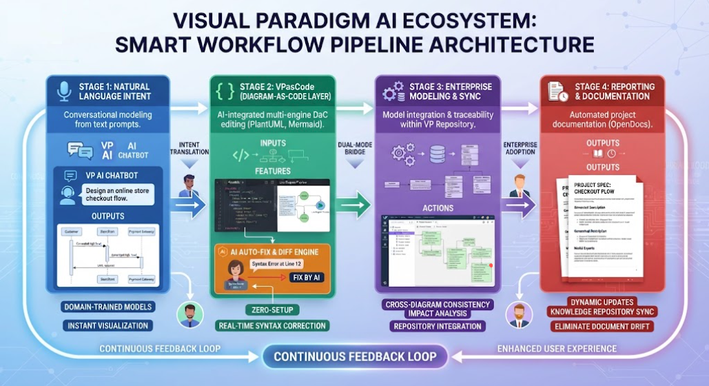
The landscape of software architecture and business process modeling is undergoing a radical transformation. Moving beyond the traditional constraints of manual drag-and-drop interfaces and tedious syntax debugging, the Visual Paradigm AI Ecosystem introduces a streamlined, conversational paradigm. This tutorial explores the architecture behind this ecosystem, guiding you through the “Smart Workflow Pipeline” that connects raw human intent directly to production-ready architecture.
1. The Core Philosophy: From Chat to Code
Traditional modeling often creates silos between the high-level conceptualization of a system and the technical execution. The Visual Paradigm AI ecosystem bridges this gap by merging generative artificial intelligence with robust enterprise modeling standards (such as UML, BPMN, ArchiMate, and SysML). The result is a continuous pipeline where a user’s text prompt can evolve into a fully documented, enterprise-grade model.
The system operates on a four-stage feedback loop, ensuring that every step from initial idea to final documentation is seamless, standardized, and error-free.
2. The Four Stages of the Smart Workflow
Understanding the architecture requires breaking down the workflow into its four distinct but interconnected stages.
Stage 1: Natural Language Intent & Conversational Generation
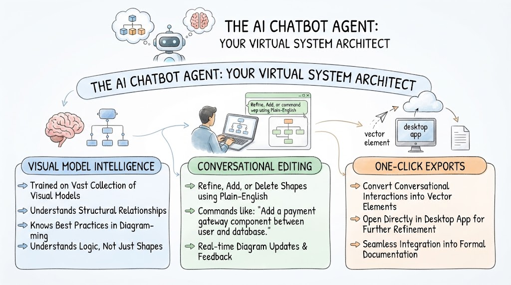
The pipeline begins with the AI Diagramming Chatbot, which acts as the natural language interface for high-level conceptualization. This stage eliminates initial friction by translating text requirements, bullet points, or system descriptions into structured, standards-compliant diagrams.
- The Process: An architect or developer provides a prompt, such as “Design an OAuth2 authentication sequence diagram” or “Design an online store checkout flow.”
- The AI Magic: Domain-trained models parse the syntax and apply structural logic rules. They map semantic inputs directly to formal specifications (like UML interactions) with a near-zero syntax error rate.
- The Output: Instant visualization of baseline models, such as Sequence Diagrams or C4 models, without manual canvas alignment.
Stage 2: Dual-Mode Bridge & Code-Level Refinement (VPasCode)
Once the initial model is generated, the workflow transitions into the VPasCode environment. This is a browser-based, zero-setup Diagram-as-Code (DaC) playground that supports major text-to-diagram standards like PlantUML, Mermaid, and Graphviz.
- Transitioning to Code: Users can click “Open in VPasCode” to move from a visual chat artifact into a text-based script representation. This provides precision tuning and programmatic control.
- Smart Error Correction: The ecosystem features an automated AI Auto-Fix syntax engine. If an adjustment introduces a syntax error, the AI detects the exact line number and offers a one-click correction button. It displays a pedagogical side-by-side code diff, explaining the resolution to the user.
Stage 3: Enterprise Modeling & Capability Mapping
The pipeline does not stop at a standalone diagram. Stage 3 connects the lightweight web tools with heavy-duty offline/online enterprise repositories via the Enterprise Desktop & Cloud Sync Bridge.
- Repository Integration: Verified assets are synchronized with the broader Visual Paradigm repository framework.
- Deep Traceability: The architecture automatically binds graphic elements to underlying model elements. This enables recursive sub-diagram expansion (drilling down from high-level components into child models) and cross-diagram consistency checks.
- Impact Analysis: Teams can perform deep requirements traceability, ensuring that design changes align with broader enterprise goals.
Stage 4: Reporting & Downstream Synchronization
The final stage ensures that the visual assets are not lost to “document drift”—the common issue where written specifications diverge from code or diagrams. This is handled by the Automated Documentation Engines (specifically OpenDocs integration).
- Dynamic Updates: Documentation updates dynamically alongside visual changes.
- Automated Specs: The system converts visual assets, data dictionaries, and architectural models into structured Markdown reports and project specifications automatically.
3. Key Technical Components Explained
To fully leverage this ecosystem, it is essential to understand the specialized modules that interact seamlessly:
The AI Diagramming Chatbot
This is your entry point. It supports over 40+ structured diagram types. Its primary role is to act as a “translator,” converting human language into the strict syntax required by engineering standards.
VPasCode (Embedded Native AI & Multi-Engine Editor)
VPasCode serves as the technical refinement layer. It is not just a code editor; it is a multi-engine compiler. It allows you to toggle between engines (e.g., switching from PlantUML to Mermaid) and provides real-time feedback loops for debugging.
The Enterprise Sync Bridge
This component is the backbone of collaboration. It ensures that models generated in conversational spaces can be pulled directly into full enterprise projects. This facilitates team collaboration and ensures that individual contributions fit into the larger architectural puzzle.
4. Summary of User Experience Enhancements
The Visual Paradigm AI Ecosystem is designed to solve three major pain points in modern software architecture:
- Zero-Friction Context Switching: Users can pivot fluidly from plain-language chat prompts to code editing, and back to visual previews, without leaving the ecosystem framework.
- Error Immunity: The self-healing AI auto-fix mechanism eliminates traditional DaC frustrations, transforming debugging into an instant, educational experience.
- Standardization without Overhead: Teams achieve rigorous adherence to formal framework structures through conversational interactions, democratizing complex architectural modeling.
By understanding this architecture, architects and developers can move beyond simple diagramming and embrace a true “Intent-to-Production” workflow.
Related posts:
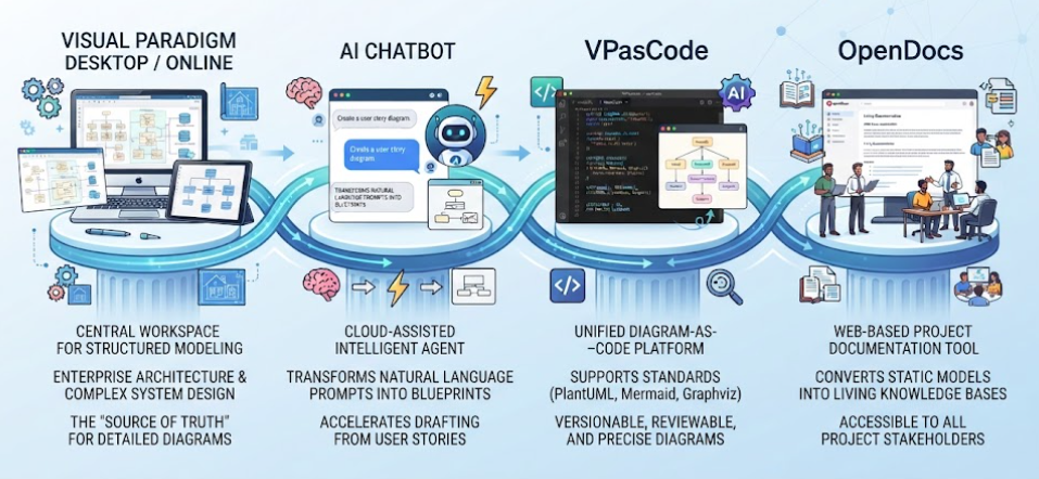 Mastering the Modern Software Design Workflow: From Ideation to Living Documentation with Visual Paradigm
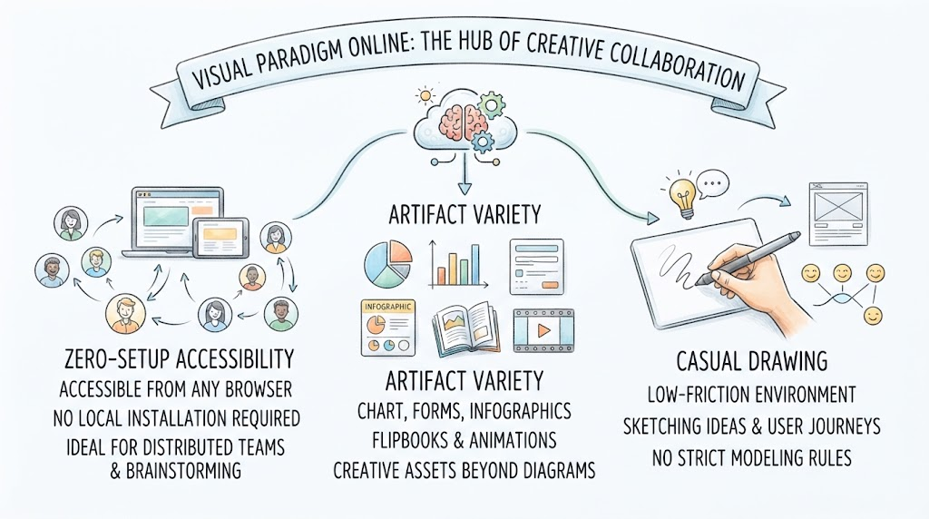 Mastering Visual Paradigm Online: A Guide to Cloud-Based Collaboration and Creative Modeling
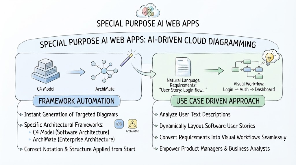 Mastering AI-Driven System Modeling: From Frameworks to Workflows
 Mastering System Architecture: How AI Chatbots Transform Visual Modeling