In the world of business process management, clarity is not just a luxury; it is a necessity. When processes become complex, the risk of misinterpretation skyrockets. This is where Business Process Model and Notation (BPMN) shines. As a standardized language, BPMN provides a visual framework that bridges the gap between business stakeholders and technical developers.
This tutorial breaks down the essential building blocks of BPMN clarity. By understanding the core elements—Gateways, Pools, Lanes, and Events—you can transform chaotic workflows into streamlined, logical diagrams.
1. Gateways: The Decision Points of Your Process
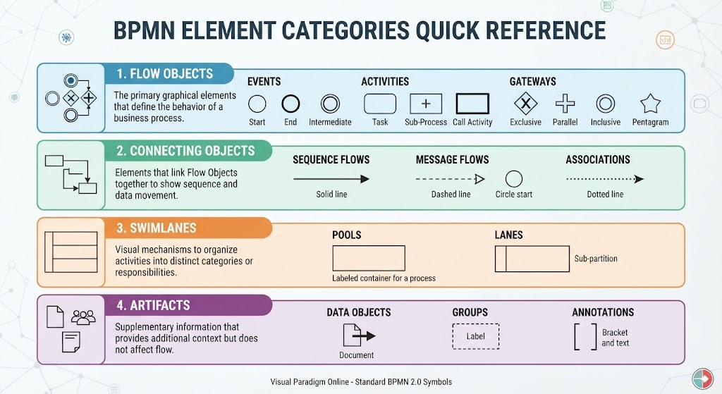
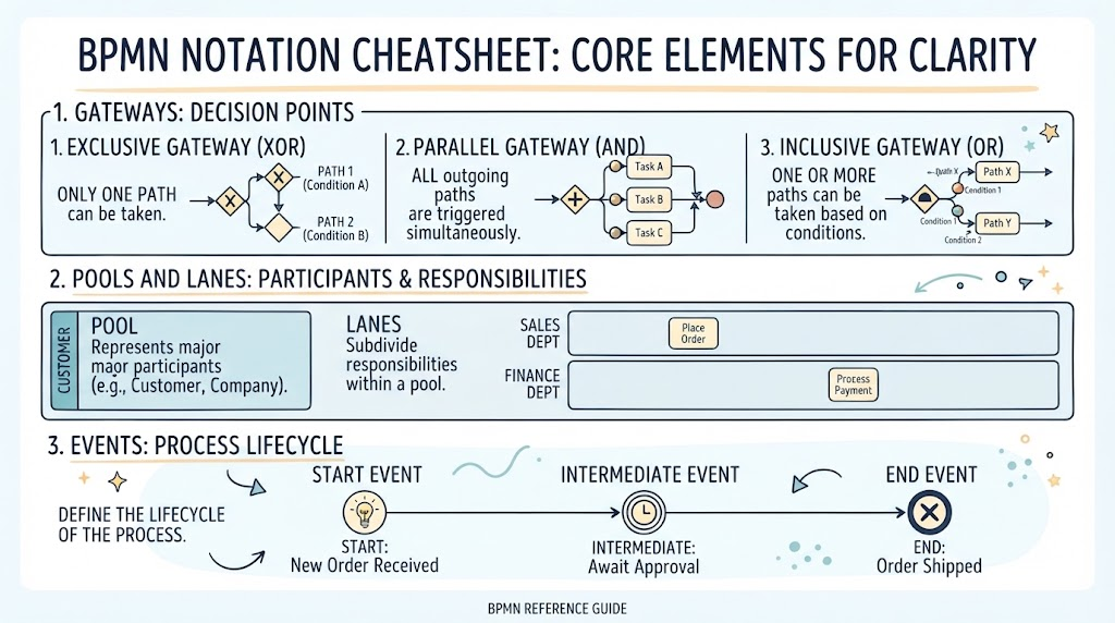
Imagine a road intersection. Depending on your destination, you might go straight, turn left, or take a detour. In BPMN, these intersections are called Gateways. They control the flow of “tokens” (work items) through the process. Understanding the three primary gateway types is crucial for defining logic.
Exclusive Gateway (XOR)
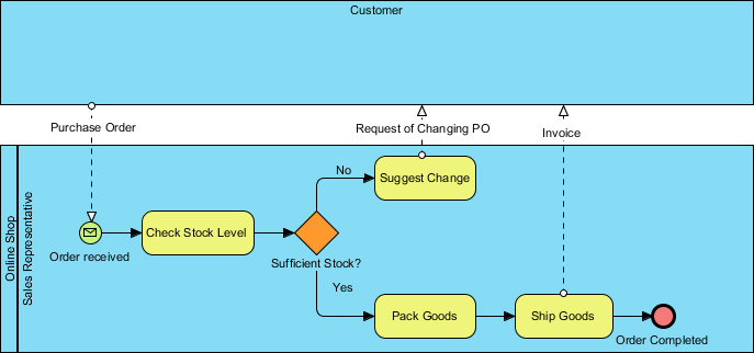
The Exclusive Gateway is your classic “Either/Or” decision point. It ensures that only one path can be taken out of the gateway, based on a specific condition.
- Visual Cue: A diamond shape with an ‘X’ inside.
- Logic: If Condition A is true, take Path 1. If Condition B is true, take Path 2. They cannot happen simultaneously.
Parallel Gateway (AND)
Sometimes, a process requires a burst of activity where multiple things happen at once. The Parallel Gateway allows you to split the flow so that all outgoing paths are triggered simultaneously. It waits until all paths are complete before merging them back together.
- Visual Cue: A diamond shape with a plus sign (+) inside.
- Logic: Task A, Task B, and Task C all start at the exact same moment.
Inclusive Gateway (OR)
Flexible logic is handled by the Inclusive Gateway. It allows for one or more paths to be taken based on conditions. This is distinct from the Exclusive Gateway because multiple conditions can be true at the same time.
- Visual Cue: A diamond shape with an ‘O’ or circle inside.
- Logic: Based on specific conditions (e.g., Condition 1 or Condition 2), the process branches out to Path X, Path Y, or both.
2. Pools and Lanes: Structuring Participants and Responsibilities
Processes rarely happen in a vacuum. They involve multiple parties and departments. BPMN uses a swimlane-like structure to organize this complexity.
Pools: The Major Participants
A Pool represents a major participant in the process. Think of this as the “container” for the process. Common examples include the Customer, the Company, or an external Supplier.
Lanes: Subdividing Responsibilities
Within a single pool, you often have different departments handling different tasks. Lanes subdivide the pool to assign specific responsibilities.
- The Sales Dept Lane: Might contain the task “Place Order.”
- The Finance Dept Lane: Might contain the task “Process Payment.”
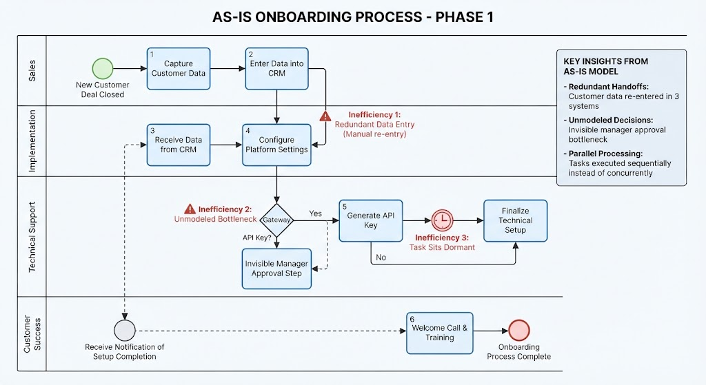
This visual separation makes it immediately obvious who is responsible for what, preventing bottlenecks and confusion regarding handoffs.
3. Events: Defining the Process Lifecycle
Every process has a beginning, a middle, and an end. Events define these lifecycle stages using specific symbols with thin circular borders.
- Start Event: The trigger that initiates the process.
- Example: A “New Order Received” triggers the workflow.
- Intermediate Event: Occurs during the process flow. These often represent a wait or a message receipt.
- Example: “Await Approval” or “Waiting for Payment.”
- End Event: The conclusion of the process.
- Example: “Order Shipped” or “Invoice Sent.”
Tooling Spotlight: Accelerating Modeling with Visual Paradigm
While understanding the theory is vital, the practical application requires robust tooling. For those looking to implement these concepts efficiently, Visual Paradigm offers a powerful environment for BPMN modeling.
AI-Assisted Modeling is a game-changer for clarity. Instead of manually dragging and dropping shapes, users can generate initial diagram structures from natural language descriptions. This significantly reduces the time spent on manual layout, allowing you to focus on the logic of your process rather than the drawing mechanics.
Furthermore, Visual Paradigm ensures your diagrams are enterprise-ready through seamless integration with UML and ArchiMate. This ensures that your process maps do not exist in isolation but align with your broader enterprise architecture goals.