


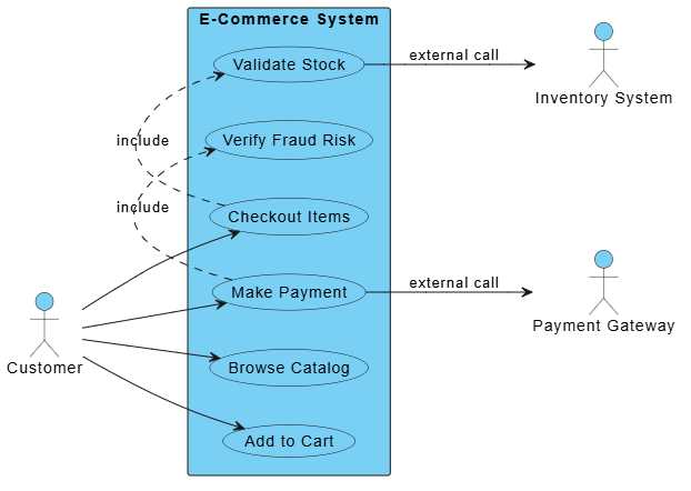
In modern software development, the gap between abstract requirements and concrete system architecture can be bridged effectively using the “Diagram-as-Code” approach. This tutorial explores how Visual Paradigm VPasCode, powered by embedded AI, transforms raw text descriptions into precise, professional-grade system diagrams.
Specifically, we will analyze the refinement of an E-Commerce System Use Case Diagram. By moving away from manual drag-and-drop interfaces, developers can utilize code syntax (PlantUML) to ensure total control over system boundaries, actor relationships, and mandatory process flows.
1. The Power of Diagram-as-Code
Traditional modeling tools often rely on visual manipulation, which can lead to “spaghetti diagrams” or inconsistent layouts. Diagram-as-Code shifts the focus to text. You write code, and the tool renders the diagram. This approach offers:
- Version Control: Diagrams become text files that can be stored in Git alongside your source code.
- Precision: Every relationship and boundary is explicitly defined in syntax.
- Scalability: It is easier to manage complex diagrams with hundreds of elements via code than via a GUI.
2. Leveraging VPasCode’s Embedded AI for Refinement
The core value proposition of VPasCode lies not just in the syntax, but in its embedded AI capabilities. The AI acts as a technical assistant that helps bridge the gap between a rough concept and a syntactically perfect diagram.
How the AI Drives the Refinement Process
Imagine you are a Product Manager or Developer starting with a textual requirement. Here is how the AI workflow functions to generate the E-Commerce diagram shown above:
- Initial Generation: You input a prompt describing the system: “Generate a use case diagram for an e-commerce system with a customer, payment gateway, and inventory system.” The AI creates a basic structure.
- Identifying Mandatory Flows: The AI analyzes the context and suggests that certain steps are mandatory. For example, “Checkout” isn’t just a single action; it includes “Validate Stock” and “Verify Fraud Risk.”
- Syntax Correction & Optimization: The AI ensures that the
includerelationships are drawn correctly using dotted lines with arrows, distinguishing them from direct associations.
3. Deconstructing the E-Commerce Architecture
Let’s walk through the specific technical elements of the diagram generated by VPasCode. This example demonstrates how to model an E-Commerce System using PlantUML syntax.
A. Defining Actors and External Systems
The diagram starts by defining the entities interacting with the system. In VPasCode, these are defined using the actor keyword.
- Customer: The primary human user initiating the flow.
- Payment Gateway (PG): An external system actor handling financial transactions.
- Inventory System (IS): An external system actor managing stock levels.
B. System Boundaries
The rectangle "E-Commerce System" defines the scope. Everything inside this box belongs to the application logic; everything outside is an external dependency. This visual boundary is crucial for developers to understand what code they are responsible for writing versus what is a third-party API call.
C. Use Cases and Relationships
The diagram uses specific relationship types to clarify the logic:
- Direct Associations: The solid lines from the Customer to Browse Catalog or Add to Cart represent direct user interactions.
- External Calls: The arrows pointing to Inventory System and Payment Gateway labeled “external call” indicate API interactions. The code explicitly defines these as
Customer --> PG : external call. - Include Relationships: This is the most critical architectural detail. The diagram uses
.> : includeto show that Checkout Items must call Validate Stock. You cannot have a checkout without validating stock. Similarly, Make Payment must include Verify Fraud Risk.
4. The PlantUML Syntax Breakdown
To replicate this architecture, developers use the following PlantUML structure within VPasCode. This code snippet demonstrates how the visual elements map to text commands:
Code Structure Explanation
@startuml initiates the diagram. The left to right direction command sets the layout orientation. The skinparam packageStyle rectangle ensures the system boundary looks like a standard box rather than a rounded folder.
The core logic is handled by the relationships:
(Checkout Items) .> (Validate Stock) : includecreates the dotted arrow indicating a mandatory dependency.(Validate Stock) --> IS : external callconnects the internal process to the external actor.
5. Conclusion
By utilizing VPasCode’s AI-driven refinement, teams can move rapidly from high-level requirements to precise architectural blueprints. The ability to define include relationships and external boundaries programmatically ensures that the resulting diagram is not just a picture, but a rigorous specification of the software’s behavior.
Related posts:
 Mastering System Architecture with VPasCode: A Guide to Just-in-Time Diagram-as-Code
 Mastering Diagram-as-Code: A Deep Dive into VPasCode’s Embedded AI Architecture
 Mastering Diagram-as-Code with VPasCode: Architecture, AI, and Workflow
 Mastering Dynamic Documentation: How Visual Paradigm OpenDocs Bridges the Gap Between Code and Context