In the world of software architecture, clear communication is just as important as writing clean code. Visual diagrams help developers, stakeholders, and designers understand the structure of a system before a single line of code is written. PlantUML is a powerful tool that allows you to create these diagrams using a simple, text-based syntax. This tutorial will break down the foundational concepts of PlantUML Class Diagrams, focusing on how to structure classes, define visibility, and map relationships between objects.
1. The Anatomy of a Class
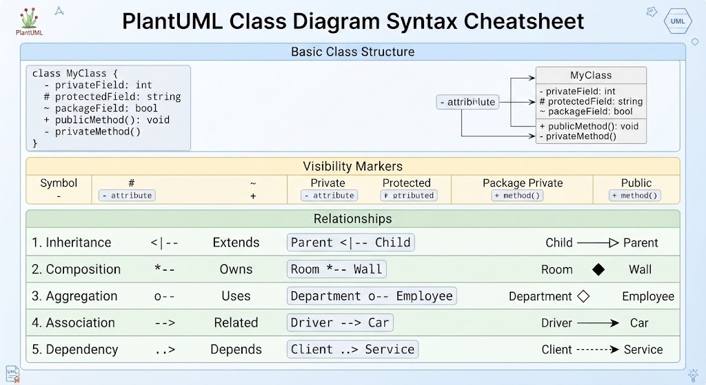
At the heart of any class diagram is the Class itself. In PlantUML, defining a class is remarkably straightforward. You start with the class keyword, followed by the name of your class. All the internal details—such as attributes (variables) and methods (functions)—are enclosed within curly braces { }.
Consider the following structure shown in our guide:
- Declaration:
class MyClass { ... } - Attributes & Methods: Listed inside the braces.
Each line inside the class block represents a specific member of the class. The magic happens in the symbols you place before the name of the attribute or method. These symbols dictate the Visibility Marker, which controls access levels.
Understanding Visibility Markers
Visibility markers are crucial for encapsulation, a core principle of Object-Oriented Programming (OOP). PlantUML uses specific characters to represent these standard UML visibility levels:
-(Private): This member is accessible only within the class itself. In the diagram, you will see attributes prefixed with a hyphen, like- privateField: int.#(Protected): This member is accessible within the class and its subclasses (children). For example,# protectedField: string.~(Package Private): Also known as “default” visibility, this member is accessible to any class within the same package or namespace. Example:~ packageField: bool.+(Public): This member is accessible from anywhere. This is the most open visibility level. Example:+ publicMethod(): void.
2. Mapping Relationships Between Classes
Classes rarely exist in isolation. They interact, depend on, and inherit from one another. PlantUML uses specific arrow syntax to visualize these relationships. Understanding the difference between these arrows is vital for accurately modeling system architecture.
Inheritance (Extends)
Inheritance allows a class to inherit attributes and methods from another class. In PlantUML, this is represented by a solid line with a hollow triangle arrowhead pointing to the parent class. The syntax is <|--.
Example: Child <|-- Parent implies that Child extends Parent.
Composition (Owns)
Composition represents a "strong" ownership relationship. If the parent object is destroyed, the child object cannot exist independently. Visually, this is a solid line with a filled diamond at the parent's end. The syntax is --.
Example: A Room has a Wall. If the room is demolished, the wall is gone. Room -- Wall.
Aggregation (Uses)
Aggregation is a "weak" relationship. It implies that the child object can exist independently of the parent. Visually, this looks like Composition but with a hollow (empty) diamond at the parent's end. The syntax is o--.
Example: A Department contains Employees. If the department is dissolved, the employees still exist as people. Department o-- Employee.
Association (Related)
Association represents a general connection or relationship between two classes. It is often used to show that one class "knows about" or uses another. This is depicted as a simple solid line with an arrowhead. The syntax is -->.
Example: A Driver drives a Car. Driver --> Car.
Dependency (Depends)
Dependency is a relationship where a change in one class might affect another. It is the weakest form of relationship. Visually, it is a dashed line with an arrowhead. The syntax is ..>.
Example: A Client uses a Service. If the service changes, the client must adapt. Client ..> Service.
Conclusion
By mastering these basic syntax elements—class structure, visibility markers, and relationship arrows—you can create robust, standard-compliant UML diagrams using PlantUML. Whether you are designing a complex enterprise system or a simple application, starting with a clear class diagram will save you time and confusion during the development phase.