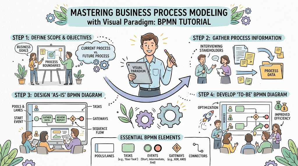
In the realm of business process improvement, the transition from a fragile “As-Is” state to a robust “To-Be” state is often best understood through visual modeling. The diagram provided illustrates a sophisticated redesign of an order fulfillment system. It moves beyond simple linear workflows to incorporate dynamic decision logic, automated interventions, and external partnerships.
This tutorial breaks down the system architecture, the modeling concepts used in the diagram, and the strategic logic behind this resilient “To-Be” process.
Understanding the Visual Language
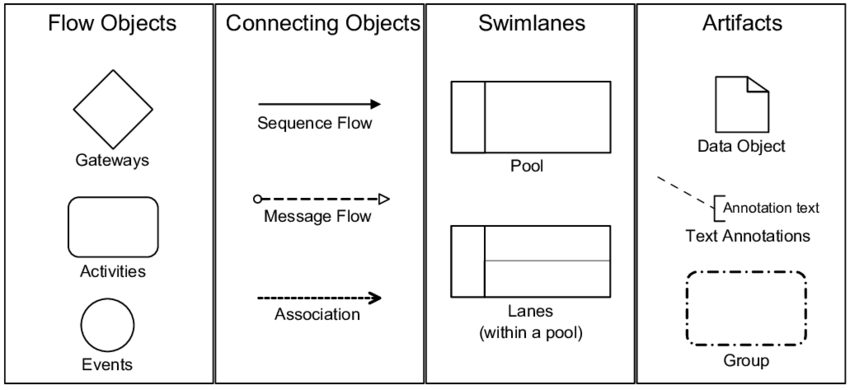
Before diving into the process flow, we must decode the symbols used in this BPMN (Business Process Model and Notation) diagram. The visual language tells a story about how data moves and decisions are made:
- Green Circle (Start Event): The process initiates here when an “Order Received” event occurs.
- Yellow Rounded Rectangles (Tasks): These represent specific activities or actions, such as “Check Availability” or “Update Inventory.”
- Blue Rounded Rectangles (Sub-processes): These represent complex groups of activities. For instance, Automated Instant Reorder or Dynamic Sourcing from Partner Network likely contain multiple internal steps.
- Diamond Shapes (Gateways): These are decision points where the path splits based on a condition (e.g., “Available?”).
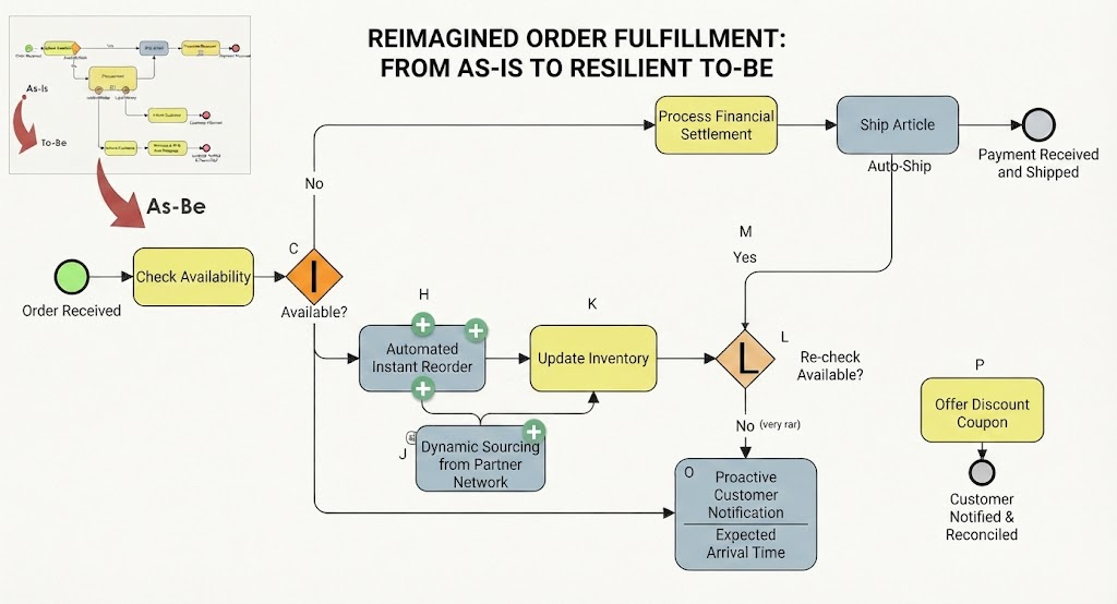
- Red Arrow (The Transition): The large red arrow labeled “As-Be” signifies the strategic shift from the old, likely manual, fragmented system (shown in the top-left inset) to the new, integrated system.
The “To-Be” Process Walkthrough
The core of this architecture lies in how it handles uncertainty. In the “To-Be” model, the system doesn’t just wait for stock; it actively manages inventory availability.
1. The Trigger and Initial Check
The process begins at the green circle with an Order Received. The first logical step is a task to Check Availability. This is not a passive check; it is the gateway to the rest of the fulfillment logic.
2. The Inventory Dilemma: A Decision Tree
Immediately following the availability check is a diamond gateway labeled C with the condition “Available?”. This is the critical pivot point of the entire diagram:
- The “No” Path (Inventory Shortage): If the item is not available, the process does not simply stop or alert a human. It automatically branches into a proactive solution.
- The “Yes” Path (Standard Fulfillment): If the item is available, the process moves to the standard fulfillment path (labeled “M”), which leads to financial settlement and shipping.
3. The Proactive “Resilience” Layer
The most innovative part of this architecture is how it handles the “No” scenario (when stock is low). Instead of a manual intervention, the system enters a loop of automated and collaborative problem-solving:
- Automated Instant Reorder: The system triggers a task to immediately reorder the item from the primary source. This reduces latency.
- Dynamic Sourcing from Partner Network: Simultaneously, the system engages with external partners. This Sub-process represents a network of suppliers that can fulfill the order if the primary source cannot.
- Proactive Customer Notification: While the system is working to solve the inventory gap, it initiates communication with the customer. The system provides an Expected Arrival Time, managing customer expectations transparently.
4. The Feedback Loop (The “Re-check”)
The diagram includes a secondary gateway labeled L with the condition “Re-check Available?”. This is a classic control loop concept. After triggering the reorders and sourcing, the system must verify if the solution worked.
- If Yes: The flow merges with the standard path to proceed to Process Financial Settlement and Ship Article.
- If No (Very Rare): In the unlikely event that the system cannot source the item even after all automated attempts, it triggers a final fallback: Offer Discount Coupon. This acts as a service recovery mechanism to retain customer loyalty despite a failed transaction.
Key Modeling Concepts for Business Improvement
When analyzing this diagram, several key concepts emerge that are essential for modernizing business processes:
1. As-Is vs. To-Be Gap Analysis
The inset in the top-left corner visually represents the Gap Analysis. The “As-Is” state (likely a linear, manual, or siloed process) is contrasted against the “To-Be” state. The gap between them is filled by the introduction of automation, decision logic, and external connectivity.
2. Exception Handling
Traditional processes often fail when exceptions occur. This diagram is designed for resilience. It anticipates the exception (out of stock) and provides a pre-defined, automated path to resolve it. This is a hallmark of high-performance system architecture.
3. Customer-Centric Visibility
The inclusion of the Proactive Customer Notification sub-process highlights a shift in focus. The system is no longer just about moving boxes; it is about maintaining trust. By updating the customer on expected arrival times automatically, the business reduces anxiety and support ticket volume.
4. Automation and Integration
The diagram demonstrates the power of integrating disparate systems. The Automated Instant Reorder and Dynamic Sourcing blocks imply that the Order Management System (OMS) is talking to the Inventory Management System (IMS) and potentially a Supplier Portal. This integration eliminates the “human hand-off” that usually causes delays.
Conclusion
This architectural diagram represents a mature evolution of order fulfillment. By moving from a reactive “As-Is” state to a proactive “To-Be” state, the business transforms potential failures (stockouts) into managed exceptions. The use of decision gateways, feedback loops, and automated notifications ensures that the system is not just efficient, but also resilient and customer-focused.