


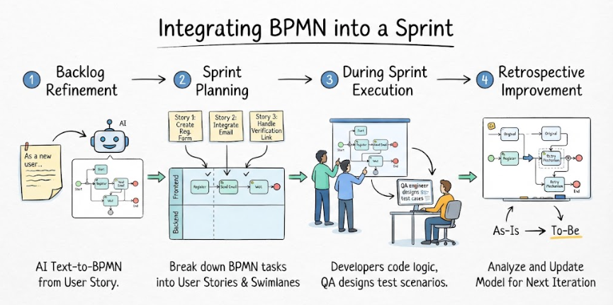
In modern software development, the gap between abstract requirements and executable code often leads to miscommunication and rework. This tutorial explores a powerful methodology for bridging that gap: integrating Business Process Model and Notation (BPMN) directly into the Agile sprint lifecycle. By utilizing intelligent tools like Visual Paradigm, teams can transform static user stories into dynamic, visual system architectures that guide development, testing, and continuous improvement.
Phase 1: Backlog Refinement & AI-Driven Modeling
The process begins before a single line of code is written. In the standard Agile workflow, the “Backlog Refinement” phase is where user stories are analyzed. However, text-based descriptions can be ambiguous. By applying AI Text-to-BPMN technology, teams can instantly visualize the logic.
The User Story Input
Consider a typical requirement: “As a new user, I want to register so that I can access the platform, requiring email verification.”
Using AI-assisted modeling, this text is parsed and converted into a preliminary BPMN diagram. This immediate visualization helps stakeholders identify missing logic, such as error handling or specific data flows, before planning begins.
The Initial Process Model
The AI generates a linear flow that establishes the core system architecture:
- Start Event: The user initiates the process.
- Register Task: The system captures user input.
- Send Email Task: The system triggers an external service to generate a verification link.
- Wait for Click Event: The process pauses, waiting for user action (asynchronous behavior).
- Verify Task: The system validates the token and grants access.
- End Event: The registration is complete.
Phase 2: Sprint Planning & Swimlane Decomposition
Once the high-level process is modeled, the next step is to decompose it into actionable tasks for the development team. This is where Swimlanes become critical. Swimlanes visually segregate responsibilities, typically separating Frontend (User Interface) from Backend (Server Logic and API).
Mapping Tasks to User Stories
The visual model allows Product Owners to break the process down into specific development stories:
- Story 1: Create Registration Form (Frontend)
Developers focus on the UI components required for the “Register Task,” ensuring the form captures all necessary fields.
- Story 2: Integrate Email Service (Backend)
Backend engineers implement the “Send Email Task,” configuring the SMTP server or third-party email service.
- Story 3: Handle Verification Link (System)
This complex task covers the “Wait for Click” and “Verify” steps. It requires handling asynchronous API calls and database state management.
Phase 3: Sprint Execution & QA Strategy
During the sprint, the BPMN diagram serves as the “Single Source of Truth.” It provides developers with a clear map of the logic flow, reducing the need for constant clarification.
Visual Logic for Developers
Developers refer to the swimlanes to understand exactly where their code fits. For example, the diagram clearly shows that the Wait for Click event is a gateway between the backend sending an email and the frontend receiving a callback.
Test Case Generation for QA
Quality Assurance (QA) engineers leverage the diagram to design comprehensive test suites. Unlike text-based requirements, a BPMN diagram explicitly shows paths and gateways.
- Happy Path Testing: Validate the standard flow from Start to End.
- Exception Path Testing: Identify where the process might fail (e.g., if the email service returns an error).
- State Verification: Ensure the system correctly handles the wait state before verifying the link.
Phase 4: Retrospective & As-Is/To-Be Analysis
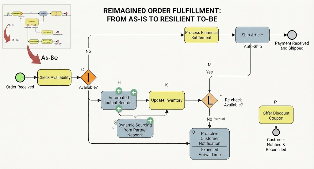
The final phase of the sprint cycle is the Retrospective. Here, the team analyzes performance and identifies areas for improvement. BPMN facilitates this by allowing for As-Is vs. To-Be analysis.
Identifying Bottlenecks
Suppose the retrospective reveals that the “Send Email Task” frequently fails due to network latency or rate limiting. In a traditional workflow, this might just be noted as a bug. In a BPMN-driven workflow, the model is updated to reflect the reality.
Modeling Improvements
The team modifies the diagram to include a “Retry Mechanism” sub-process. This might involve adding a gateway that checks if an email was delivered; if not, the system loops back to resend the email a specific number of times.
- As-Is Model: Represents the current state where email delivery is a single shot.
- To-Be Model: Represents the improved state with a loop for retries, ensuring higher system reliability for the next sprint.
Conclusion
Integrating BPMN into Agile sprint planning transforms the development lifecycle from a linear text-based process into a dynamic, visual architecture. By utilizing AI-driven tools like Visual Paradigm, teams can:
- Enhance Communication: Visuals eliminate ambiguity between stakeholders and developers.
- Reduce Rework: Logic is validated before coding begins.
- Support Continuous Improvement: The “To-Be” modeling approach ensures the system architecture evolves with every sprint.
By adopting this approach, development teams achieve greater clarity, efficiency, and alignment, ensuring that the final product matches the intended design perfectly.
Related posts:
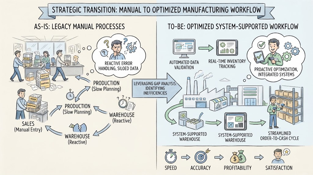 Navigating the Strategic Transition: From Manual Chaos to Optimized Efficiency
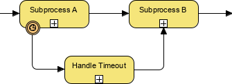 BPMN Diagram Subprocess Timeout Handling
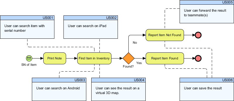 Bridging the Gap: Integrating BPMN Process Flows with Agile User Stories in Visual Paradigm
 Reimagining Business Resilience: A Visual Guide to the As-Is vs. To-Be Order Fulfillment Architecture