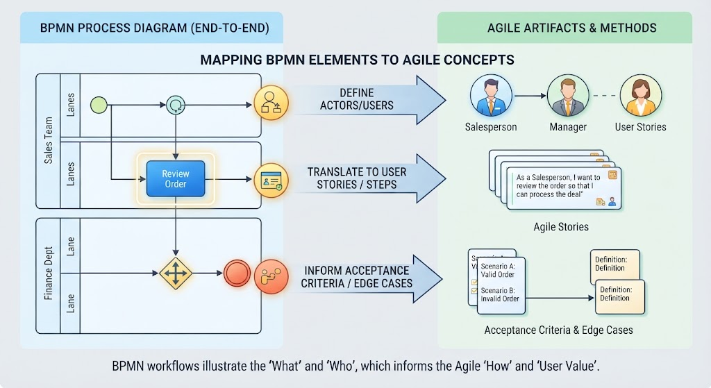
In the world of software development and business process management, a common disconnect exists between how business processes are modeled and how they are implemented in agile sprints. On one side, you have BPMN (Business Process Model and Notation), which excels at visualizing complex workflows. On the other, you have Agile methodologies, which focus on iterative delivery and user value. This tutorial explores the critical bridge between these two worlds: translating BPMN diagrams into actionable Agile artifacts.
The Core Philosophy: “What” vs. “How”
Before diving into the specific elements, it is crucial to understand the conceptual difference between the two methodologies. As illustrated in our mapping diagram:
- BPMN illustrates the ‘What’ and ‘Who’: It defines the scope of the process, the actors involved, and the logical flow of information.
- Agile defines the ‘How’ and ‘User Value’: It focuses on the specific functionality required by the user and the value that functionality delivers.
By mapping these concepts, we ensure that the technical implementation (Agile) perfectly aligns with the business reality (BPMN).
1. Defining Actors: BPMN Pools and Lanes
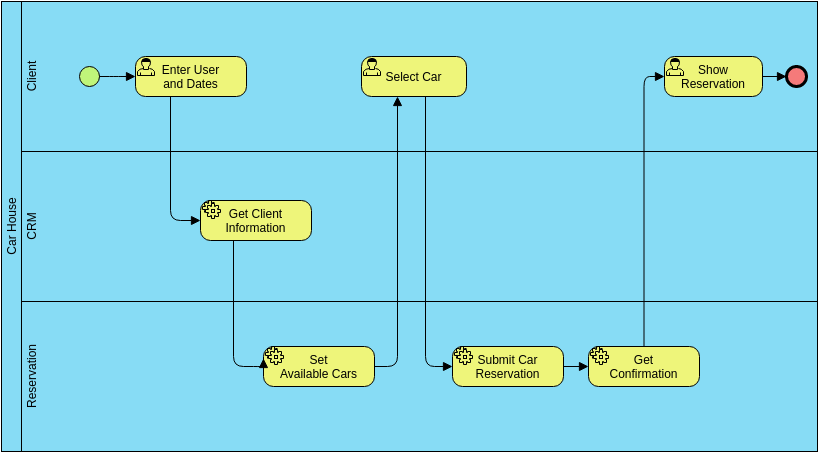
One of the first steps in analyzing a BPMN diagram is identifying the participants in the process. In BPMN, these are represented by Pools (distinct organizations) and Lanes (specific roles or departments within those organizations).
Mapping to Agile
When translating this to Agile, the Lanes directly define the Actors or Users for your User Stories. You cannot write a valid User Story without knowing who is performing the action.
- BPMN Element: A Lane labeled “Sales Team” or “Finance Dept”.
- Agile Equivalent: The persona (e.g., Salesperson, Manager, Finance Officer).
Example: If your BPMN diagram shows a “Finance Dept” lane, your backlog must contain stories written for the Finance Department, not the Sales Team.
2. Translating Actions: Tasks to User Stories
The heart of a BPMN diagram is the sequence of Tasks or Activities. These are the specific boxes that represent work being done. For example, a blue box might represent the action “Review Order.”
The Translation Formula
To convert a BPMN Task into an Agile User Story, you simply apply the standard “As a… I want… So that…” format using the Actor identified in the previous step.
Example from Diagram:
- BPMN Task: Review Order
- Actor (from Lane): Salesperson
- Agile User Story: “As a Salesperson, I want to review the order so that I can process the deal.”
This step transforms a static diagram node into a dynamic requirement that drives development.
3. Handling Complexity: Gateways and Acceptance Criteria
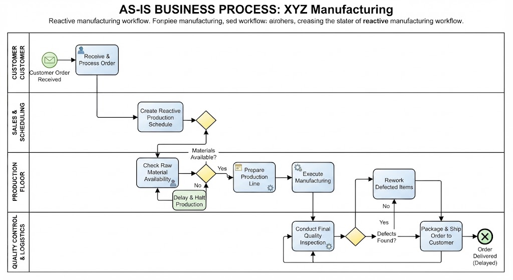
BPMN is excellent at showing logic. Gateways (the diamond shapes) and Events (the circles) represent decision points, branching paths, and potential errors (like a failure path).
From Logic to Testing
While a User Story defines the happy path (the goal), the Gateways and Events in the BPMN diagram inform the Acceptance Criteria and Edge Cases. Every branch coming out of a Gateway represents a condition that must be tested.
- Identify the Gateway: Look for the diamond shape (e.g., an XOR gateway).
- Identify the Outcomes: Look at the arrows leaving the diamond. One might say “Valid Order,” and another might say “Invalid Order.”
- Define Acceptance Criteria:
- Scenario A (Valid): “System accepts the order and moves it to the next lane.”
- Scenario B (Invalid): “System flags the order and sends it to the rejection queue.”
Conclusion
Understanding the relationship between BPMN and Agile allows teams to build systems that are not only technically sound but also perfectly aligned with business needs. By treating BPMN Actors as User Personas, Tasks as User Stories, and Gateways as Acceptance Criteria, you create a seamless translation from business analysis to agile development.