In the complex landscape of software engineering, communication is often just as critical as code execution. The Unified Modeling Language (UML) serves as the universal visual language that bridges the gap between abstract architectural concepts and concrete implementation details. At the heart of this visual lexicon lies the UML class diagram, the most fundamental and widely used component for documenting system structure.
Whether you are architecting a massive enterprise system, designing a microservice architecture, or sketching a quick prototype for stakeholder alignment, understanding how to properly structure the UML class box is essential. This guide breaks down the anatomy of a class box, explores how to adapt its level of detail to fit your audience, and provides practical insights into using professional modeling tools like Visual Paradigm.
1. The Anatomy of the UML Class Box
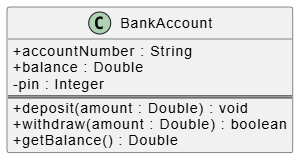
The UML class box is a simple yet powerful visual representation that encapsulates a software entity’s structure, behavior, and responsibilities. Visually, it is a rectangular box divided into three distinct sections, each serving a specific purpose in defining the class.
The Three Sections of a Class
- Top Section (Class Name): This area holds the name of the class. In standard UML notation, this text is usually centered, bolded, and underlined. It acts as the identifier for the entity within the system.
- Middle Section (Attributes): Also known as the data section, this compartment lists the properties or variables that the class holds. These represent the state of the object.
- Bottom Section (Operations): This area defines the methods or functions available to the class. These represent the behavior of the object—what it can do.
2. Decoding Visibility and Access Modifiers
One of the most critical aspects of UML modeling is defining how different parts of the system interact with one another. The UML class box uses specific symbols to denote the visibility of attributes and operations. This concept is crucial for maintaining data integrity and enforcing encapsulation.
Understanding the Symbols
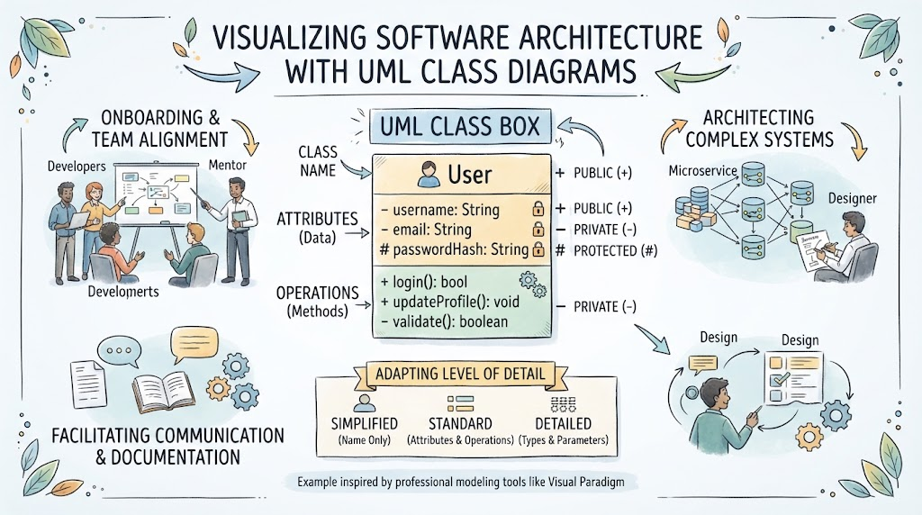
As illustrated in the standard notation, the symbols preceding the names in the attribute or operation sections dictate their accessibility:
- Public (+): Denoted by a plus sign (
+). These members are accessible from any other class in the system. They form the public interface of your class. - Private (-): Denoted by a hyphen (
-). These members are strictly accessible only within the class itself. They are the internal secrets of the object. - Protected (#): Denoted by a hash symbol (
#). These members are accessible by the class itself and any classes that inherit from it (subclasses). This is vital for object-oriented inheritance hierarchies.
3. Practical Example: Modeling the “User” Class
To visualize these concepts, let’s examine a practical example often seen in system design: the User class. This class represents a distinct entity within an application and typically holds sensitive data and functional capabilities.
Consider the structure of a User class in a modern application:
- Attributes: It likely needs to store a
usernameandemail(Public), but thepasswordHashmust be strictly hidden (Private or Protected) for security. - Operations: It needs methods to
login()(Public),updateProfile()(Public), and perhaps an internal method likevalidate()(Private) that checks data integrity before saving.
This separation ensures that while the system can verify a user’s identity via a login method, the actual hash of their password remains inaccessible to external modules, adhering to security best practices.
4. Adapting the Level of Detail
A common challenge in software modeling is determining how much detail to include. A diagram that is too complex can confuse stakeholders, while one that is too simple may be useless to developers. UML class diagrams offer flexibility to adapt to the audience.
Simplified vs. Detailed Views
Depending on the stage of development or the target reader, you can modify the class box in three ways:
- Simplified (Name Only): Used for high-level architecture or onboarding. The box contains only the class name. This is excellent for “Facilitating Communication” with non-technical stakeholders or for a quick “sketching” session.
- Standard (Attributes & Operations): The most common format. It includes the names of attributes and methods but omits their specific data types. This is ideal for code-first developers who need to understand the interface without getting bogged down in syntax.
- Detailed (Types & Parameters): Used for technical specification and documentation. This includes data types (e.g.,
String,int) and method parameters. This is essential for “Architecting Complex Systems” where precision is required.
5. The Role of Modeling Tools
While hand-drawing diagrams has its charm, professional-grade modeling tools like Visual Paradigm offer robust features for creating, managing, and collaborating on UML diagrams. These tools allow you to:
- Switch dynamically between simplified and detailed views.
- Automatically generate code skeletons from your class diagrams.
- Ensure consistency across large enterprise systems.
By mastering the theoretical foundations of the UML class box and utilizing practical applications, you will be equipped to create diagrams that effectively communicate your software design intent. Whether you are onboarding new team members, documenting design decisions, or facilitating cross-functional discussions, a well-crafted UML diagram remains an invaluable asset in the software engineering toolkit.