


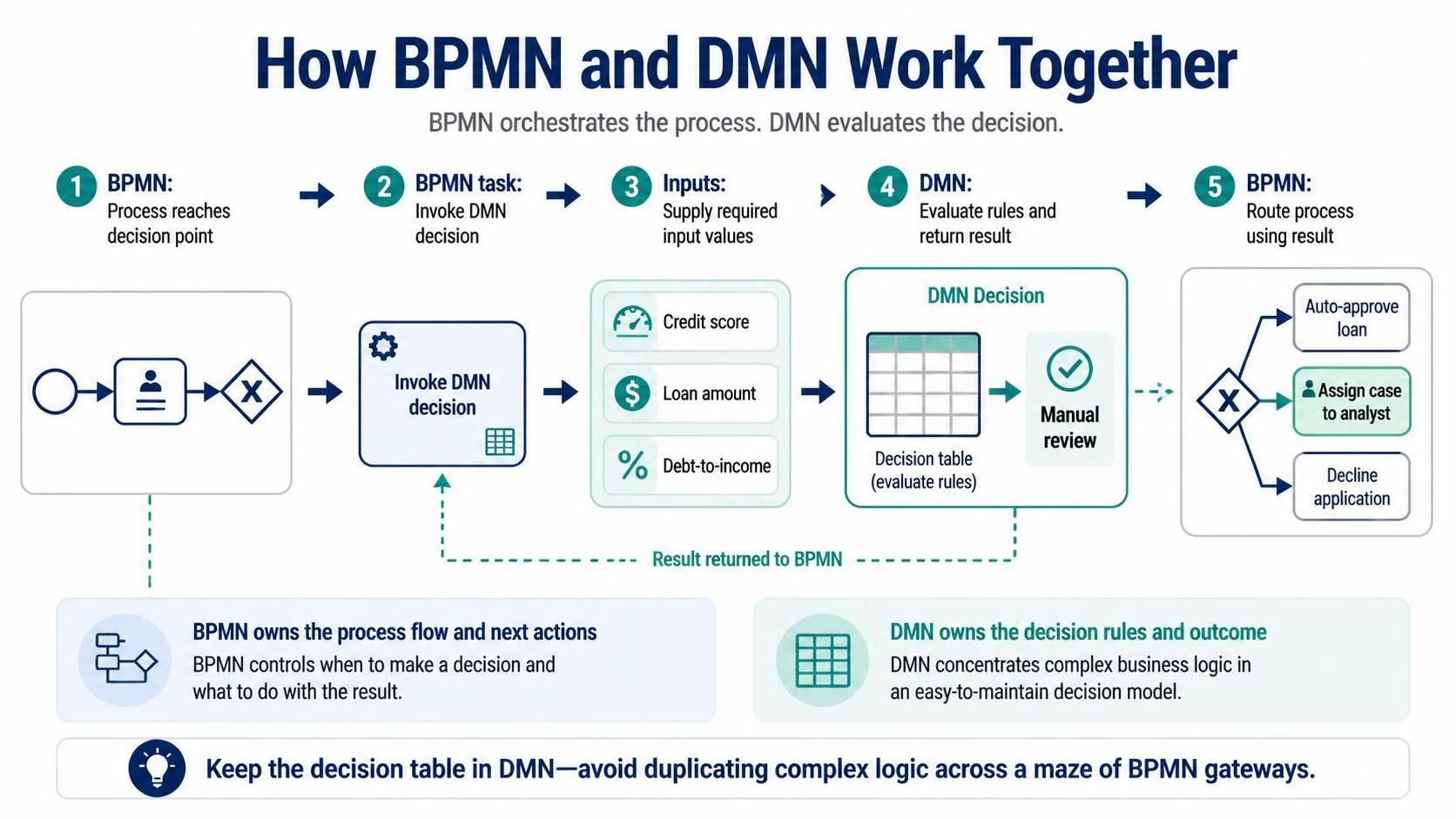
In the realm of business process management and automation, one of the most critical architectural patterns is the decoupling of process logic from decision logic. As illustrated in the diagram “How BPMN and DMN Work Together,” organizations achieve agility by allowing Business Process Model and Notation (BPMN) to orchestrate the flow, while Decision Model and Notation (DMN) handles the complex evaluation rules.
This tutorial breaks down the specific integration steps shown in the visual, explaining how a process moves from a standard activity to an intelligent decision point, and finally to a routed outcome.
The 5-Step Integration Pattern
The diagram outlines a precise, five-step lifecycle that occurs every time a process needs to make a data-driven decision. This pattern ensures that the process model remains clean and readable.
1. The Decision Point in BPMN
The sequence begins when the BPMN process reaches a logical fork. In the diagram, we see a standard flow moving from a Start Event to a Task (represented by the User icon), arriving at an Exclusive Gateway (the diamond with the “X”).
Normally, a developer might be tempted to write complex “if-else” logic directly into the conditions of the gateway. However, in a mature architecture, this gateway represents a pause in the process, waiting for external intelligence to determine the path.
2. Invoking the DMN Decision Service
Instead of hardcoding logic, the process executes a specific task designed to call an external service. The diagram labels this as “Invoke DMN decision.”
- Visual Representation: In tools like Visual Paradigm, this is often modeled as a Service Task or a specific “Invoke Decision” task.
- Technical Action: The process engine sends a request to the DMN engine. This acts as a bridge, connecting the flow of the business process with the logic of the business rules.
3. Supplying Contextual Inputs
A decision engine cannot work in a vacuum; it requires data. The diagram clearly identifies three specific input variables required for this decision:
- Credit Score: Represented by a gauge icon.
- Loan Amount: Represented by a dollar sign icon.
- Debt-to-Income Ratio: Represented by a percentage icon.
The BPMN process maps its current data (variables stored in the process context) to these required input fields. This decoupling allows the process to change without touching the decision table, and vice versa.
4. Evaluating Rules and Returning Results
Once the inputs are received, the DMN engine takes over. The diagram shows a Decision Table inside the DMN box. This is where the heavy lifting happens.
Unlike a process diagram which is linear, a decision table is a matrix of inputs and outputs. The engine evaluates the “Credit score,” “Loan amount,” and “Debt-to-income” against the defined rules. The output in this specific example is a string value: “Manual review”.
5. Routing the Process
The result is returned to the BPMN engine, which stores it in the process variables. The process then resumes execution at the Exclusive Gateway.
- The gateway evaluates the returned value.
- If the value is “Manual review,” the flow is directed to the task “Assign case to analyst.”
- Other paths might lead to “Auto-approve loan” or “Decline application.”
Separation of Concerns: BPMN vs. DMN
The bottom section of the diagram emphasizes the philosophical difference between these two standards:
BPMN owns the Process Flow:
BPMN controls when a decision is made and what to do with the result. It manages the human tasks, the service calls, and the overall timeline of the case.
DMN owns the Decision Logic:
DMN concentrates complex business logic in an easy-to-maintain model. It focuses purely on the mathematical or logical evaluation of the inputs.
Why Use This Pattern? The “Maze of Gateways” Problem
The diagram concludes with a crucial insight: “Keep the decision table in DMN—avoid duplicating complex logic across a maze of BPMN gateways.”
Without this integration, a loan approval process might look like a spaghetti chart of diamond shapes (gateways) connected by complex boolean expressions. If a rule changes (e.g., the interest rate threshold changes), the analyst would have to hunt down every single gateway condition in the process diagram.
By using DMN, the complexity is hidden inside a single, tabular decision model. The process diagram remains clean, showing only the high-level steps: Start -> Review -> Decide -> Act -> End.