Welcome to this comprehensive tutorial on business process modeling. In this guide, we will deconstruct a standard Leave Management Process diagram created using Visual Paradigm. This example serves as a foundational blueprint for understanding how organizations streamline employee requests, approval hierarchies, and administrative record-keeping using Business Process Model and Notation (BPMN).
By analyzing this diagram, you will learn how to map out complex workflows, define user roles through swimlanes, and implement logic-based decision gates. Whether you are a business analyst or a developer, mastering this visual language is essential for creating compliant and efficient systems.
1. Understanding the Swimlanes: Defining Organizational Roles
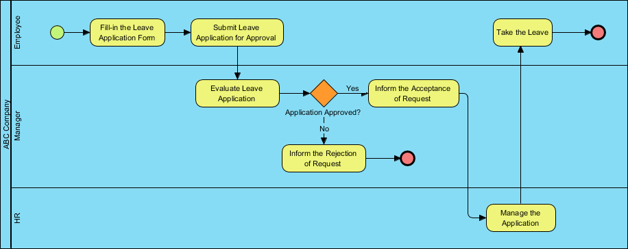
The most striking feature of this BPMN diagram is its structure. It utilizes Swimlanes (also known as Pools and Lanes) to visually separate responsibilities. This ensures that every step in the process is clearly assigned to a specific actor. The diagram is divided into three distinct horizontal lanes:
- Employee: The initiator of the process. This lane represents the individual requesting time off.
- ABC Company Manager: The decision-maker. This lane contains the evaluation logic and the critical approval gate.
- HR: The administrative body. This lane handles the final management of the application once approved.
This separation is crucial for system architecture because it dictates which user interface screens or backend permissions are triggered at each step of the workflow.
2. The Employee Journey: Initiating the Request
The process begins on the top left with a Start Event (the green circle), indicating the entry point of the workflow. The flow is linear and straightforward for the employee:
- Fill-in the Leave Application Form: This is the first Task (represented by a rounded rectangle). In a software system, this would trigger a form generation event.
- Submit Leave Application for Approval: Once the form is complete, the process flow moves downward, crossing from the Employee lane into the ABC Company Manager lane. This transition signifies a hand-off of authority or data.
3. The Manager’s Role: Evaluation and Logic Gates
The process now enters the critical decision-making phase within the middle lane. The Manager receives the submission and performs an evaluation.
The Evaluation Task
The Evaluate Leave Application task represents the review period where the manager assesses the request against company policies, budget, and team availability.
The Exclusive Gateway
Following the evaluation, we encounter a Gateway (the diamond shape labeled Application Approved?). This is a pivotal concept in BPMN. It introduces logic to the system:
- The “Yes” Path: If the application is approved, the flow moves to the right. The system must automatically inform the requester of the acceptance.
- The “No” Path: If the application is rejected, the flow moves downward. The system must inform the requester of the rejection. This path leads immediately to an End Event (the red circle), signifying the termination of the process for this specific request.
4. The HR Role: Finalization and Record Keeping
If the application is approved, the process does not end immediately. It flows down to the HR lane. This highlights the importance of data integrity and audit trails.
- Manage the Application: This task is performed by HR. It likely involves updating the master employee database, deducting leave days from the annual balance, and generating an official record.
5. Completion and the Employee Returns
After HR manages the application, the flow arrow points back up to the Employee lane. This completes the administrative loop.
- Take the Leave: The employee is now authorized to take their time off. This is the final action task.
- End Event: The process concludes with a red circle, indicating the successful completion of the entire workflow.
Summary of Key BPMN Concepts
By building this diagram in Visual Paradigm, you have utilized several core technical concepts:
- Sequence Flow: The solid black arrows that dictate the order of operations.
- Tasks: The yellow rounded rectangles representing actionable work items.
- Gateways: The diamond shapes used to branch the workflow based on conditions (Yes/No).
- Events: The circles representing the start, intermediate, and end points of the process.
This structured approach ensures that the final software implementation will be robust, handling both successful approvals and rejections gracefully while maintaining clear separation of duties.