Welcome to this comprehensive tutorial on one of the most critical components of Business Process Model and Notation (BPMN): the Parallel Gateway. Whether you are a business analyst, a process engineer, or a software developer, understanding how to model concurrent tasks is essential for accurate system design. In this guide, we will walk you through the architectural concepts of splitting and merging processes, specifically focusing on the use of Visual Paradigm to bring these diagrams to life.
What is a Parallel Gateway?
In the world of BPMN, a gateway acts as a traffic controller for the flow of your process. The Parallel Gateway, visually represented as a diamond shape containing a plus sign (+), is unique because it does not make decisions based on conditions (like “If X, then Y”). Instead, it manages the flow of execution based on concurrency.
Unlike an Exclusive Gateway (XOR), which forces the process to choose one path, a Parallel Gateway (AND) ensures that all specified paths are taken. It is the fundamental tool used to model scenarios where multiple activities must happen simultaneously or where multiple activities must finish before the process can continue.
Core Concept 1: The Splitting Gateway (Forking)
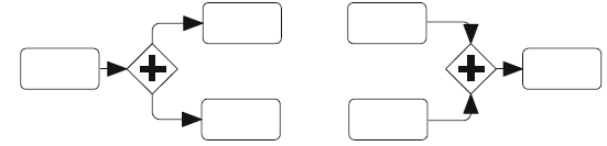
Let’s look at the left side of the diagram provided. This represents a Splitting Parallel Gateway. Imagine a scenario where a user submits an order. After the order is received, the system needs to perform three distinct actions immediately:
- Charge the credit card.
- Update the inventory.
- Send a confirmation email.
These three actions do not depend on each other; they can happen at the exact same time. This is where the Splitting Gateway is used.
How it works:
- Token Arrival: A single token arrives at the gateway from the previous activity.
- The Split: The gateway “fires.” It does not wait or choose. It instantly creates a copy of the token for every outgoing sequence flow.
- Parallel Execution: The process branches into multiple paths that are processed in parallel. The process flow effectively “forks.”
Modeling in Visual Paradigm:
When using Visual Paradigm to create this split:
- Drag a Parallel Gateway from the palette onto your canvas.
- Connect your incoming flow (e.g., “Order Received”) to the gateway.
- Drag three outgoing flows to three separate service tasks (e.g., “Charge Card”, “Update Inventory”, “Send Email”).
- Note: You do not need to add any conditions (like “Yes” or “No”) to the outgoing lines. The gateway implies that all paths are active.
Core Concept 2: The Merging Gateway (Joining)
Now, look at the right side of the diagram. This represents a Merging Parallel Gateway, also known as a Synchronizing Gateway. After the parallel tasks described above are completed, the process must converge before moving to the next phase (e.g., “Ship Order”).
How it works:
- Independent Completion: The three parallel tasks run independently. The inventory update might finish in 2 seconds, while the email takes 5 seconds.
- The Wait: The Merging Gateway acts as a gatekeeper. It waits. It will not allow the process to move forward until it has received a token from every single incoming flow.
- Synchronization: Once the last task finishes and the final token arrives, the gateway synchronizes the flow and releases a single token to the outgoing sequence flow.
This ensures that you don’t ship the order until the inventory is actually updated and the customer has been notified.
Modeling in Visual Paradigm:
- Drag a Parallel Gateway onto the canvas.
- Connect the three outgoing flows from your parallel tasks (Charge Card, Update Inventory, Send Email) to this gateway.
- Draw a single outgoing flow from the gateway to the next step (“Ship Order”).
Visual Paradigm + AI: The Modern Modeling Workflow
Traditionally, creating these diagrams required dragging and dropping shapes manually. While effective, it can be slow when iterating through complex scenarios. With the integration of AI in Visual Paradigm, the modeling process has evolved.
Traditional Modeling vs. AI-Assisted Modeling
| Aspect | Traditional Approach | AI-Assisted Approach (VPasCode) |
|---|---|---|
| Creation Speed | You must manually drag every gateway, connect every line, and align the shapes. | Use the VPasCode plugin or AI chatbot. Simply type: “Create a process where a user places an order, then split into parallel tasks for billing and shipping.” |
| Accuracy | High risk of syntax errors (e.g., forgetting to synchronize a gateway) when doing it manually for large models. | AI ensures BPMN syntax rules are strictly followed. It automatically creates the correct XOR or AND gateways based on your context. |
| Iteration | Changing a path requires manual editing of the flow lines and potentially re-arranging the canvas. | Use conversational commands: “Add a parallel check for fraud detection before billing.” The AI automatically inserts the gateway and adjusts the flow. |
Summary of the Architecture
To summarize the architecture shown in your diagram:
- Left Side (Split): This is the Fork. It takes a single thread of execution and multiplies it into multiple threads. It is used for concurrent execution.
- Right Side (Merge): This is the Join. It takes multiple threads of execution and consolidates them into a single thread. It is used for synchronization.
By mastering these two concepts, you can design robust workflows that accurately reflect the complexity of real-world systems. Whether you are building them manually in Visual Paradigm or using the power of AI to generate them, understanding the logic of the Parallel Gateway is key to professional BPMN modeling.