In the world of software engineering and systems analysis, clarity is king. Before writing a single line of code, architects and developers must define exactly what the system is supposed to do. This is where the Use Case Diagram shines. Unlike other diagrams that focus on internal code structures, a use case diagram presents the system from the outside, looking in. It bridges the gap between business requirements and technical implementation by identifying the actors that interact with the system and the goals they pursue.
The Anatomy of a Use Case Diagram
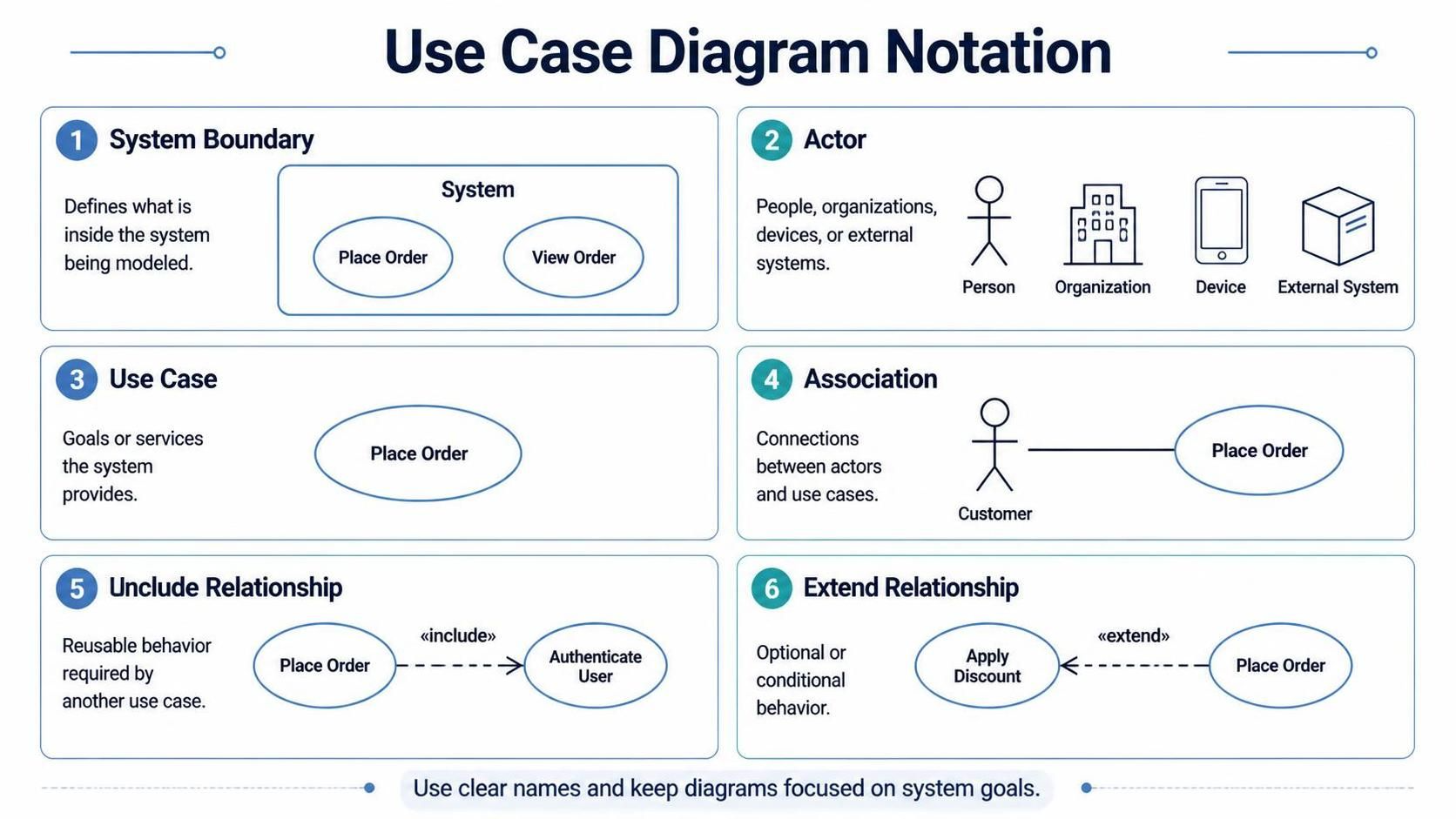
A use case diagram is deceptively simple in its visual language, yet powerful in its ability to define system boundaries. To build a robust model, you need to master six fundamental elements. Let’s break down the notation shown in the diagram and how it translates into your modeling logic.
1. The System Boundary
The system boundary is the container that defines the scope of your model. It is a rectangle that encapsulates the use cases. Everything inside the box is part of the system’s functionality, while everything outside is external to it. When you define a boundary, you are essentially answering the question: “What is included in our current development sprint versus what is an external dependency?”
2. Identifying Actors
Actors represent the roles played by users or external entities that interact with the system. They are typically represented by stick figures, but the notation is flexible. An actor can be:
- A Person: A human user like a “Customer” or “Admin”.
- An Organization: A department or company entity.
- A Device: A hardware component like a mobile phone or a sensor.
- An External System: Another software system or API that interacts with yours.
Crucially, actors are always located outside the system boundary.
3. Defining Use Cases
Use cases are the ellipses (ovals) inside the system boundary. Each use case represents a specific goal or service the system provides to an actor. For example, “Place Order” or “View Order.” A good use case name should be a verb-object pair that describes a complete unit of functionality.
4. Associations
The association is the solid line connecting an actor to a use case. It represents a communication flow. If there is a line between a “Customer” and “Place Order,” it implies the Customer can initiate that process. In many modeling tools, the direction of the association can be toggled to indicate who initiates the interaction, though often it is bidirectional by default.
5. Include Relationships
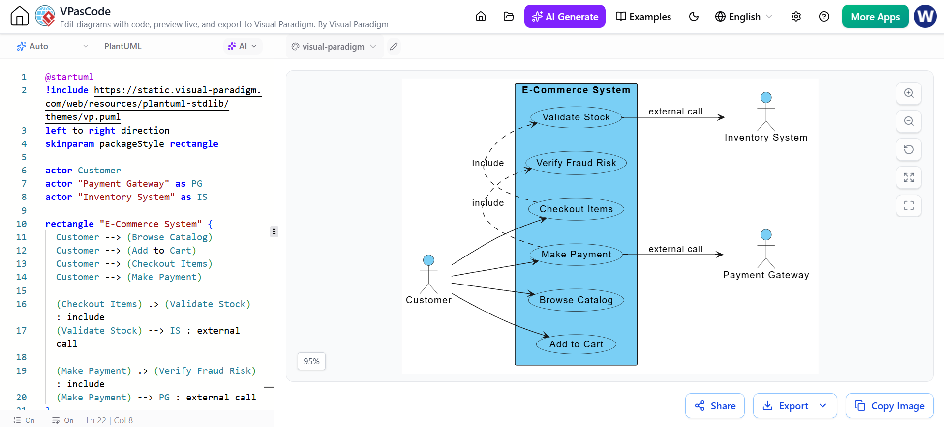
Not all use cases are created equal. Sometimes, one use case is a mandatory prerequisite for another. This is modeled using an Include relationship. It is depicted as a dashed line with an open arrow pointing to the included use case, labeled with the keyword «include».
Think of “Include” as “Always.” If a user wants to Place Order, they must always Authenticate User. The included behavior is reusable and mandatory.
6. Extend Relationships
While “Include” represents mandatory behavior, “Extend” represents optional or conditional behavior. It is also a dashed line with an open arrow, but the arrow points back to the base use case, labeled with the keyword «extend».
This allows you to model exceptions or enhancements without cluttering the main flow. For instance, the base use case might be Place Order, but if the user has a coupon, they can Apply Discount. The discount is an extension of the ordering process.
Modeling with VPasCode
Visual Paradigm (VP) streamlines this process through its VPasCodeTool, allowing you to define diagrams using natural language-like syntax. This approach reduces the friction of dragging and dropping shapes and ensures your diagram is strictly compliant with UML standards.
Here is how you would translate the concepts above into VPasCode syntax to generate a diagram:
@startuml
left to right direction
skinparam packageStyle rectangle

' Define the System Boundary
rectangle "Order Processing System" {
  usecase "Place Order" as UC1
  usecase "View Order" as UC2
  usecase "Authenticate User" as UC3
  usecase "Apply Discount" as UC4
}

' Define Actors (External)
actor "Customer" as C
actor "Payment Gateway" as PG

' Define Associations
C -- UC1
C -- UC2
UC1 -- PG

' Define Include Relationship (Mandatory)
UC1 ..> UC3 : <>

' Define Extend Relationship (Optional/Conditional)
UC4 ..> UC1 : <>
@enduml
In this snippet, notice how the syntax explicitly separates the system boundary (the rectangle) from the external actors. The relationships are defined using the ..> syntax with specific stereotypes («include» and «extend») to ensure the arrows point in the correct direction, adhering to the rules established in the notation guide.
Best Practices for Effective Modeling
When constructing these diagrams, keep your focus on system goals. Avoid modeling internal implementation details like “Calculate Tax” or “Update Database”—these are tasks the system performs, not goals the user achieves. Instead, group them under higher-level goals like “Place Order.”
Furthermore, ensure that your use case names are clear and concise. A diagram is a communication tool; if the names are ambiguous, the architecture will suffer. By mastering the System Boundary, Actors, Associations, and the nuances of Include vs. Extend relationships, you create a blueprint that is both technically accurate and easily understood by stakeholders.