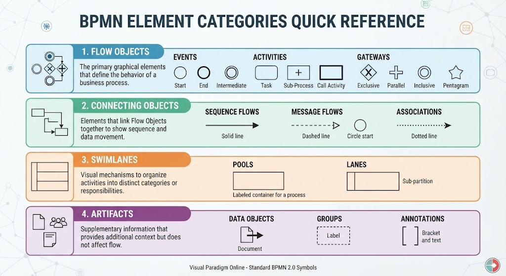
In the world of business process management, clarity is king. Whether you are mapping out a complex supply chain or a simple customer onboarding workflow, using a standardized notation is essential for effective communication. This tutorial explores the foundational building blocks of Business Process Model and Notation (BPMN), specifically focusing on the four key element categories organized by Visual Paradigm Online.
By understanding these symbols—Flow Objects, Connecting Objects, Swimlanes, and Artifacts—you can build process models that are universally understood, precise, and actionable.
1. Flow Objects: The Engine of Your Process
Flow Objects are the primary graphical elements that define the behavior of a business process. They represent the “what” and “when” of your workflow. Visual Paradigm Online categorizes these into three distinct sub-types:
Events
Events are represented by circles and indicate something that happens during a process. They are the triggers and outcomes.
- Start Event: A thin circle indicating where the process begins.
- End Event: A thick circle indicating where the process concludes.
- Intermediate Event: A circle with a double line, representing an occurrence that happens between the start and end of a process.
Activities
Activities are the tasks or work performed within the process. They are depicted as rounded rectangles.
- Task: The basic unit of work.
- Sub-Process: A task that contains further detail, often indicated by a plus (+) sign.
- Call Activity: A reference to a reusable process defined elsewhere.
Gateways
Gateways are the decision points that control the divergence and convergence of paths. Choosing the right gateway is critical for accurate modeling logic.
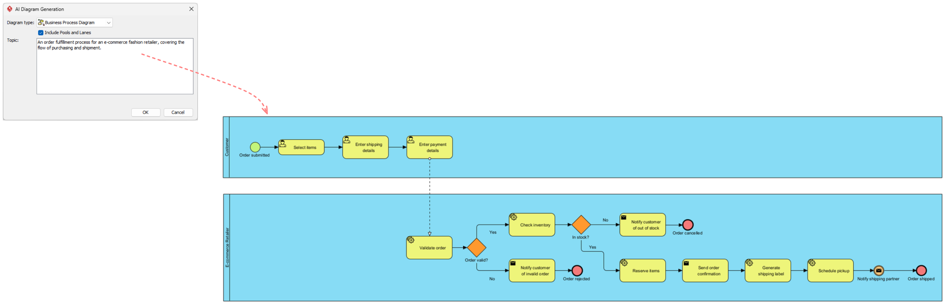
- Exclusive Gateway (XOR): Represented by a diamond with an ‘X’. Only one path is taken based on a condition (e.g., “Is stock available?”).
- Parallel Gateway (AND): Represented by a diamond with a plus (+). All paths are activated simultaneously.
- Inclusive Gateway (OR): Represented by a diamond with a circle. One or more paths may be taken depending on conditions.
- Pentagram Gateway: Used for complex control logic involving multiple conditions.
2. Connecting Objects: Linking the Logic
Connecting Objects link Flow Objects together to show sequence and data movement. They provide the context for how information and control flow from one element to another.
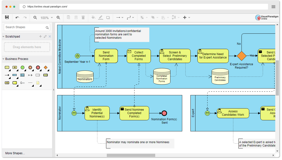
- Sequence Flows: Indicated by a solid line with an arrow. This shows the order of activities within a single process.
- Message Flows: Indicated by a dashed line with a hollow arrow. This represents the exchange of information between different participants (Pools) or separate processes.
- Associations: Indicated by a dotted line. These link artifacts (like text annotations or data objects) to flow objects to provide context without implying a sequence.
3. Swimlanes: Organizing Responsibility
Swimlanes are visual mechanisms used to organize activities into distinct categories or responsibilities. They answer the question: Who is doing this?
Pools
A Pool represents a major participant in the process, such as an entire organization or a specific system. It is a labeled container for a process.
Lanes
Lanes are sub-partitions within a Pool. They divide the process further to assign specific tasks to different roles, departments, or systems. For example, a “Customer” lane and an “Employee” lane might exist within a single “Order Processing” pool.
4. Artifacts: Supplementary Information
Artifacts provide additional context to the model but do not affect the actual flow of the process. They are the “notes” and “data” of the diagram.
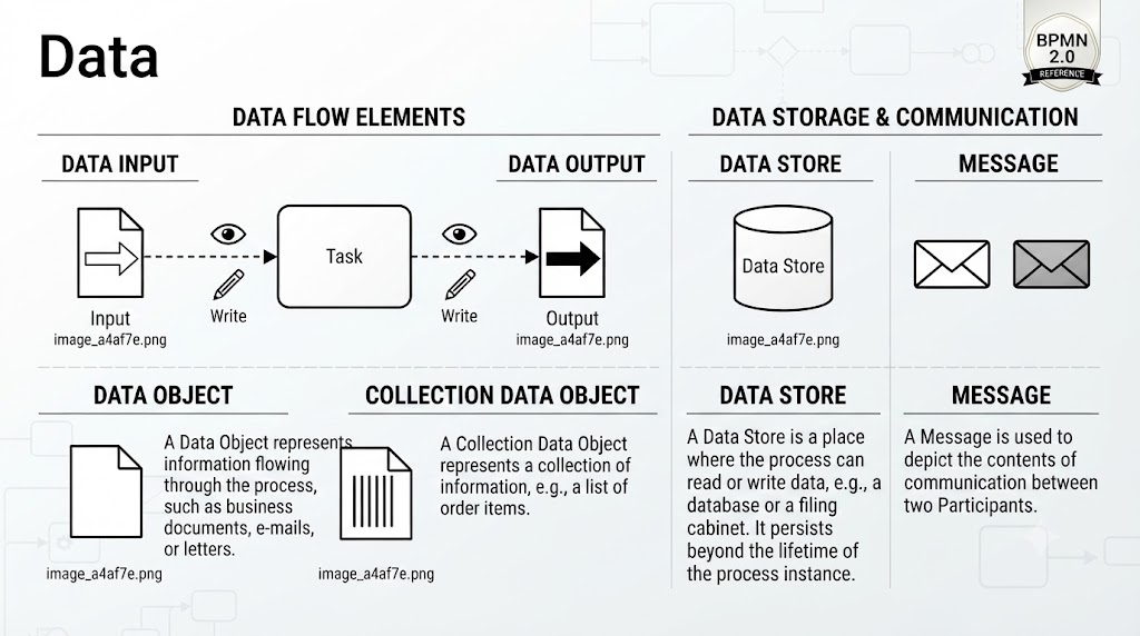
- Data Objects: Represented by a document icon with a folded corner. These show the data being created or consumed (e.g., an “Invoice” or “Purchase Order”).
- Groups: Represented by a dashed box. This allows you to visually group elements together for organizational purposes, though it does not imply a logical grouping of flow.
- Annotations: Represented by a bracket and text. These are used to add comments or explanations to specific parts of the diagram.
Deep Dive: Gateway Logic in Action
Understanding the difference between Exclusive (XOR), Parallel (AND), and Inclusive (OR) gateways is the key to modeling realistic business logic. Let’s look at a practical example: the Hiring Process.
Imagine a process where a candidate completes an interview. Following this “Interview” task, an Exclusive Gateway (XOR) is used to decide the next steps.
- Condition A (Candidate Passes): The flow moves to the “Offer Letter” task.
- Condition B (Candidate Fails): The flow moves to the “Rejection Email” task.
Crucially, in an Exclusive Gateway, both paths never occur simultaneously for the same candidate instance. If the candidate passes, the rejection email is never sent. This contrasts with a Parallel Gateway, which would send both the offer and the rejection email at the same time, leading to a logical error in this scenario.
Conclusion
By mastering these four categories—Flow Objects, Connecting Objects, Swimlanes, and Artifacts—you gain the ability to translate complex business requirements into clear, visual models. Whether you are using Visual Paradigm Online or another tool, adhering to these standard BPMN 2.0 symbols ensures that your process models are not just diagrams, but effective tools for communication and optimization.