In the complex world of organizational management, efficiency is often hindered by ambiguity. When business processes involve multiple stakeholders, intricate decision trees, and various communication channels, it becomes increasingly difficult to track how work actually moves through an organization. To combat this, the industry has adopted a universal standard: Business Process Model and Notation, commonly referred to as BPMN.
This tutorial will guide you through the fundamental concepts of BPMN, explain the visual language of the diagram provided, and demonstrate how to implement these models effectively.
What is BPMN?
BPMN is a graphical notation designed to represent the logic and sequence of activities within a business process. Think of it as a sophisticated evolution of the flowchart. While a standard flowchart might look similar, BPMN utilizes a standardized set of symbols and strict rules. This ensures that the diagram is not just a sketch, but a precise language that is understandable to all stakeholders, including:
- Business Analysts: Who need to document the “As-Is” and design the “To-Be” processes.
- Managers: Who need to visualize workflow bottlenecks.
- Developers: Who use the diagrams to automate processes (especially in BPMN 2.0).
- Other Stakeholders: Who need a clear view of responsibilities.
Understanding the Anatomy of a BPMN Diagram
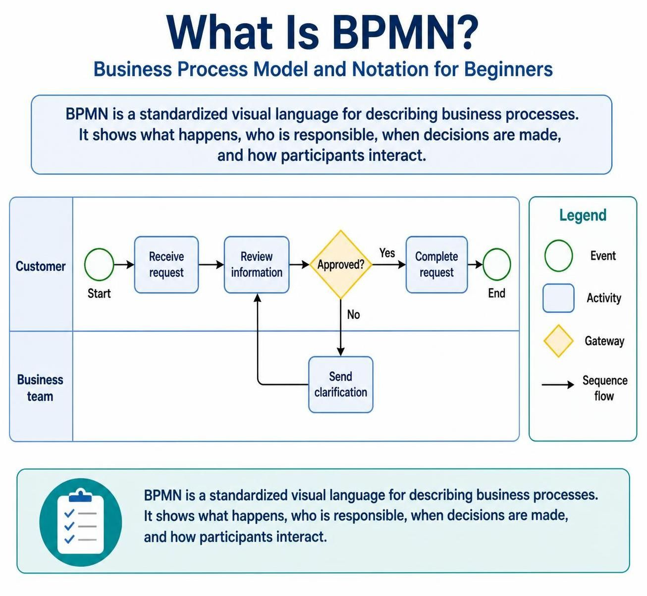
The image provided illustrates a classic BPMN process involving a “Customer” and a “Business Team.” To understand this model, we must break down the specific symbols used. The diagram is divided into “Lanes” (or Pools), which represent the different participants in the process.
1. The Participants (Lanes)
The horizontal lines dividing the diagram create distinct areas of responsibility:
- Customer Lane: Represents the external entity initiating the process.
- Business Team Lane: Represents the internal staff responsible for processing the request.
2. The Symbols (The “Visual Language”)
BPMN uses specific shapes to denote different types of actions. Based on the legend in the diagram, here is what each symbol represents:
Events (Circles)
Events are things that happen during the process. They are the triggers and the outcomes.
- Start Event: The green circle labeled “Start” indicates where the process is triggered (e.g., a customer submits a request).
- End Event: The green circle labeled “End” indicates the successful completion of the process (e.g., the request is fully resolved).
Activities (Rounded Rectangles)
Activities are the actual work being performed. In the diagram, we see blue rounded rectangles representing tasks such as:
- Receive request: The initial data capture.
- Review information: The core analysis work.
- Send clarification: A specific action taken by the business team.
- Complete request: The finalization of the task.
Gateways (Diamonds)
Gateways control the flow of the process. They act as decision points. The yellow diamond labeled “Approved?” is a gateway. It splits the path based on a condition:
- Yes: The process moves forward to “Complete request.”
- No: The process diverts to the Business Team lane to “Send clarification.”
Sequence Flow (Arrows)
The solid black arrows with open heads represent the Sequence Flow. They indicate the order in which activities are performed, moving from one symbol to the next.
Step-by-Step Logic Analysis
Let’s walk through the logic of the diagram shown in the image to understand how it functions as a system:
- Initiation: The process begins in the Customer lane when the customer initiates a request.
- Processing: The request flows to the Business Team lane. The team reviews the information provided.
- Decision Point: The team reaches the “Approved?” gateway.
- If the information is sufficient, they follow the Yes path to Complete request, and the process ends.
- If the information is insufficient, they follow the No path to Send clarification.
- Looping: After sending the clarification, the arrow loops back to the Review information activity. This creates a feedback loop, ensuring that the request is not finalized until all information is verified.
Why Standardization Matters
The diagram illustrates a process for handling a request, but BPMN is applicable to far more complex scenarios. Organizations use this standard to model:
- Processing a customer order.
- Approving a loan application.
- Handling an employee leave request.
- Responding to a customer complaint.
- Paying an invoice.
- Onboarding a new employee.
By using a common language, organizations can document processes consistently. This reduces the risk of misinterpretation and allows for better communication between technical teams and business units.
Implementing BPMN with Recommended Tooling
While the concepts are straightforward, drawing these diagrams manually can be tedious and error-prone. To truly leverage the power of BPMN, professional modeling software is essential. The standard BPMN 2.0 specification requires tools that not only draw the diagrams but also understand the semantics of the symbols.
For professionals looking to create, maintain, and analyze these complex workflows, we recommend the Visual Paradigm BPMN Tool. This tool provides a robust environment for:
- Drag-and-Drop Modeling: Easily placing events, gateways, and activities into swimlanes.
- Validation: Automatically checking for modeling errors (e.g., a gateway with no exit).
- Integration: Exporting models to executable formats or integrating with workflow engines.
- Collaboration: Allowing teams to work on the same process diagram simultaneously.
Conclusion
BPMN is more than just a drawing method; it is a bridge between business strategy and operational execution. By mastering the symbols of Events, Activities, Gateways, and Sequence Flows, you can transform chaotic workflows into clear, optimized, and communicable processes.