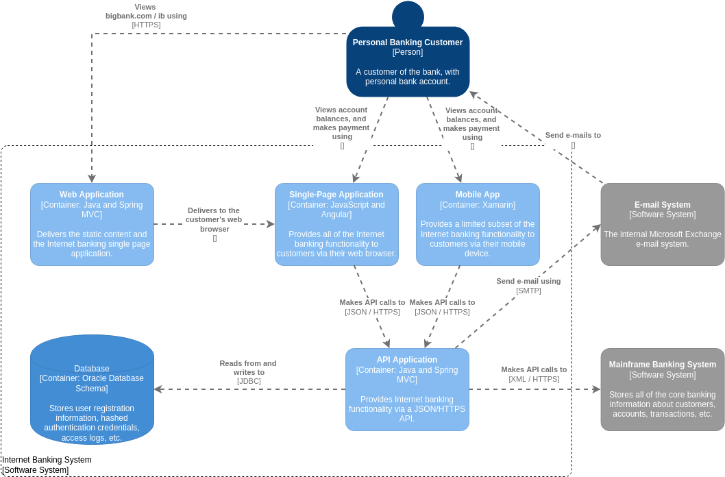
Understanding how complex software systems are built is one of the most critical skills for a modern developer or architect. In the world of software design, visual communication is often more powerful than pages of text. This tutorial breaks down a real-world example of a System Context Diagram using the C4 Model, a standard for visualizing software architecture.
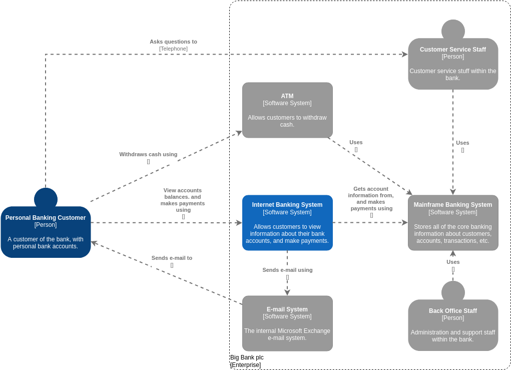
The diagram below represents a robust Internet Banking System. By analyzing its structure, we can understand how different technologies interact, where data flows, and how the system scales to meet user needs.
What is the C4 Model?
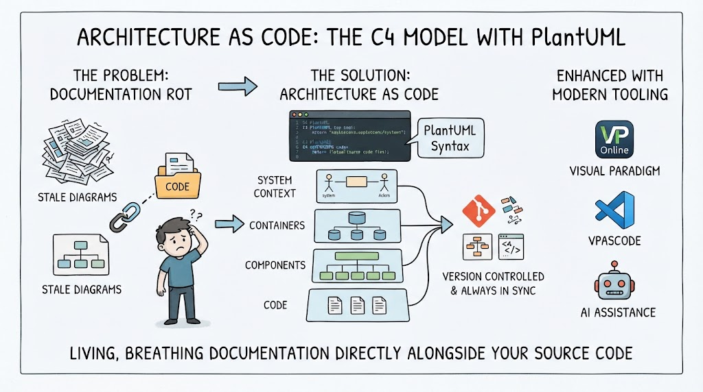
Before dissecting the specific components of this banking system, it is essential to understand the framework used to draw it. The C4 Model (Context, Container, Component, Code) is a lightweight, hierarchical approach to architecture diagrams. It allows teams to zoom in from high-level business views to low-level implementation details.
This specific diagram is a System Context Diagram (often called Level 1 in the C4 hierarchy). It answers the question: “What is the system, who uses it, and what does it talk to?”
Deconstructing the Diagram: The Building Blocks
In the C4 Model, elements are categorized by their type and role. Let’s break down the specific entities found in this banking architecture.
1. The Actor: Personal Banking Customer
At the very top sits the Personal Banking Customer, depicted as a [Person] icon. In C4 diagrams, “People” can be human users or automated agents. This node represents the primary stakeholder interacting with the system to view balances and make payments.
2. The System Boundary
Notice the large dashed line labeled Internet Banking System. This defines the perimeter of our software. Everything inside the box is part of our control; everything outside is an external dependency or actor.
3. The Containers: Technical Building Blocks
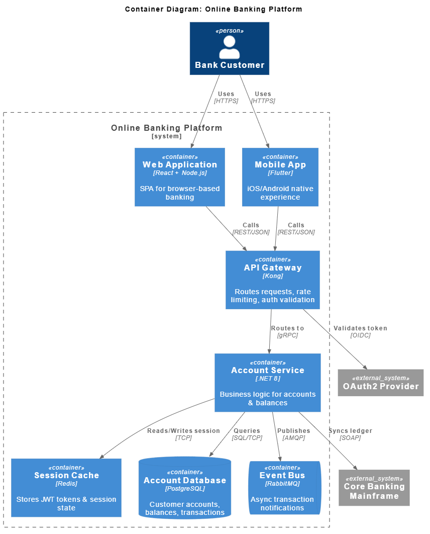
Inside the boundary, we see blue rounded rectangles. In C4 terminology, these are Containers. A container is a standalone, deployable unit of software, such as a web application, a mobile app, or a database.
- Web Application: Built with
JavaandSpring MVC. Its primary role here is to serve static content and deliver the Single-Page Application (SPA) to the user’s browser. - Single-Page Application (SPA): Built with
JavaScriptandAngular. This is the actual interactive interface the customer sees in their browser. - Mobile App: Built with
Xamarin. This provides a mobile-specific interface for iOS and Android devices. - API Application: The backend brain of the system, built with
JavaandSpring MVC. It exposes functionality via aJSON/HTTPSAPI. - Database: An
Oracle Database Schema. This stores sensitive data like user registration, credentials, and access logs.
4. External Software Systems
Outside the dashed boundary, we see gray boxes representing Software Systems. These are external systems that our system relies on but does not control.
- Mainframe Banking System: The legacy core of the bank. It stores the “source of truth” for accounts and transactions.
- E-mail System: Likely Microsoft Exchange. This handles transactional emails sent to customers.
Tracing the Data Flow: How It Works
A diagram is static; the lines connecting these boxes tell the story of how the system functions dynamically. Let’s trace the critical paths shown in the diagram.
The Customer Journey (Accessing the System)
The customer interacts with the system in two ways:
- Web Access: The customer views the system via a web browser. The arrow shows they “View… using HTTPS.” The
Web Applicationcontainer then “Delivers” theSingle-Page Applicationto the browser. - Mobile Access: The customer uses a native mobile app. The arrow indicates they “View… using HTTPS.”
Key Insight: Notice the separation between the “Web Application” and the “Single-Page Application.” This is a common architectural pattern where the Web App acts as a host or CDN (Content Delivery Network) to serve the Angular SPA, while the Mobile App is a distinct binary.
The Backend Logic (API Interaction)
Once the customer is logged in, the frontend needs data. The diagram shows:
- The Single-Page Application makes API calls to the API Application using
JSONoverHTTPS. - The Mobile App also makes API calls to the API Application using the same protocol.
This demonstrates a decoupled architecture. The frontend (Web or Mobile) does not talk directly to the database. It talks to a centralized API layer, which ensures security and allows the frontend to change without breaking the backend.
Data Storage and Legacy Integration
The API Application is the bridge between the modern web/mobile interface and the bank’s legacy infrastructure:
- To the Database: It “Reads from and writes to” the Oracle Database using
JDBC(Java Database Connectivity) for session management and logging. - To the Mainframe: It “Makes API calls” to the Mainframe Banking System using
XMLoverHTTPS. This is how it retrieves actual account balances and transaction history.
Why This Architecture Matters
This diagram illustrates several best practices in modern software engineering:
- Separation of Concerns: The API layer handles business logic, the Database handles persistence, and the Web/Mobile apps handle user experience.
- Scalability: By using a centralized API, the bank can support Web, Mobile, and potentially future channels (like a partner portal) without rewriting the core logic.
- Technology Agnosticism: The API uses standard protocols (HTTPS, JSON) to talk to the frontend, and XML to talk to the Mainframe. This allows the bank to swap out the frontend framework (e.g., moving from Angular to React) without affecting the database or mainframe.
Conclusion
This System Context diagram provides a high-level map of the Internet Banking System. It effectively communicates to stakeholders that the system is built on a modern, API-driven architecture that bridges the gap between new web/mobile technologies and legacy banking infrastructure. By following the C4 Model, teams can maintain this clarity as the system evolves over time.