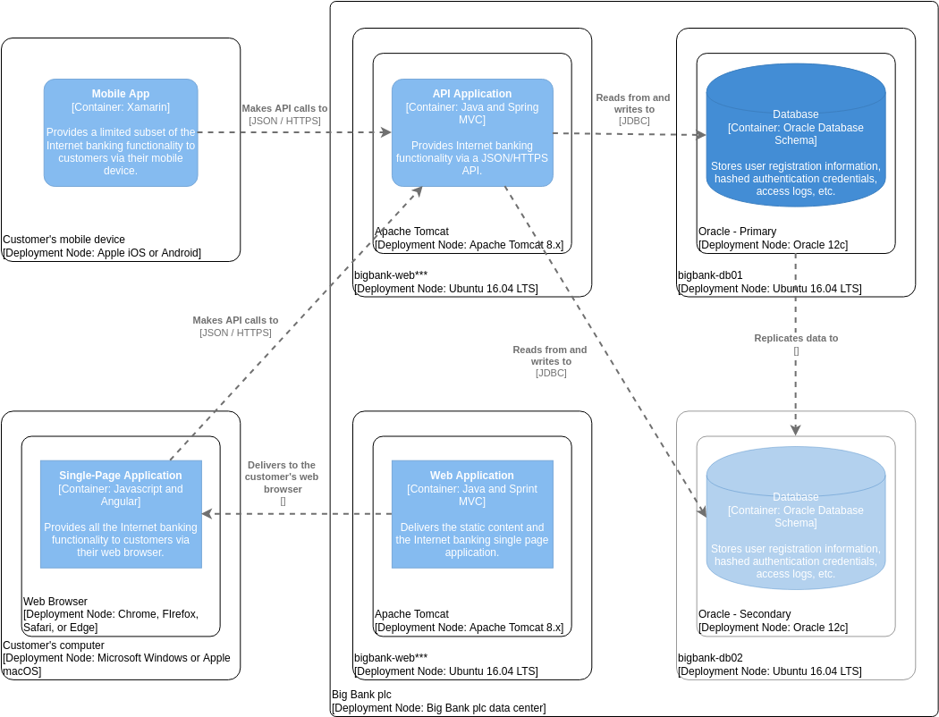
When designing complex software systems like an Internet Banking platform, visualizing how different parts of the system interact and where they physically reside is crucial. This is where the C4 Model shines. Specifically, the Deployment Diagram provides a high-level view of the runtime environment, showing the software components and the hardware they run on.
In this tutorial, we will dissect a real-world example: an Internet Banking System C4 Deployment Diagram. We will walk through the architecture layer by layer, explaining the technical relationships, the technology stack involved, and the architectural patterns at play.
1. What is a C4 Deployment Diagram?
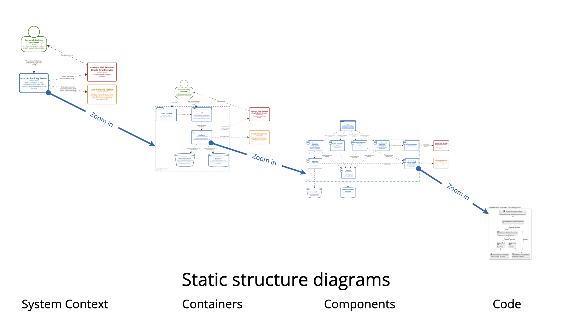
The C4 model is a hierarchical approach to software architecture documentation, consisting of four levels: Context, Container, Component, and Code. The diagram we are analyzing is a Deployment Diagram. Unlike a static context diagram, this view zooms in to show:
- Software Components: The actual applications running (e.g., Mobile App, API).
- Deployment Nodes: The physical or virtual hardware (e.g., Customer’s Device, Ubuntu Server).
- Relationships: How data flows between these nodes (e.g., API calls, Database connections).
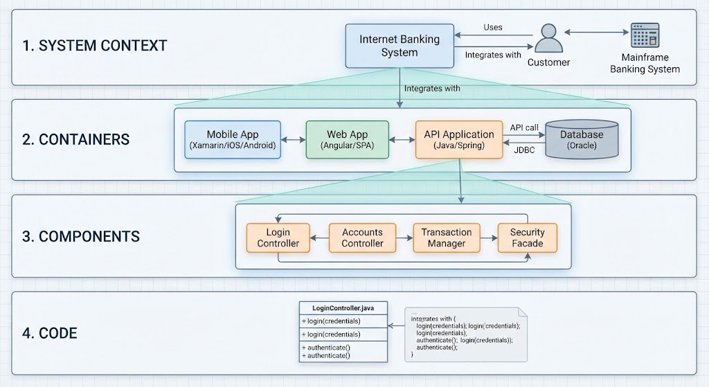
2. Deconstructing the Internet Banking Architecture
Looking at the diagram, we can divide the system into three distinct logical zones: the Customer Side (Client), the Server Side (Application Layer), and the Data Layer.
2.1 The Client Layer: Customer Access Points
The diagram illustrates two primary ways a customer interacts with the bank. This demonstrates a Multi-Channel Strategy.
- Mobile App (Top Left):
- Technology: Built using Xamarin, a cross-platform framework.
- Function: It provides a “limited subset” of functionality, likely focusing on quick checks, transfers, or alerts rather than full account management.
- Deployment Node: Runs on the customer’s physical device (Apple iOS or Android).
- Connection: It communicates via API calls (JSON/HTTPS) to the backend server.
- Web Browser (Bottom Left):
- Technology: A Single-Page Application (SPA) built with JavaScript and Angular.
- Function: Provides the full suite of internet banking functionality.
- Deployment Node: Runs on the customer’s computer (Windows or macOS) via browsers like Chrome or Firefox.
2.2 The Server Layer: The Application Backend
The central part of the diagram represents the “Big Bank plc” data center. Here, we see a separation of concerns between handling API traffic and serving web content.
- API Application (Top Center):
- Role: This is the backend engine for the Mobile App. It handles the logic for transactions and data retrieval.
- Technology: Built with Java and Spring MVC.
- Runtime: Deployed on Apache Tomcat 8.x, a standard Java servlet container.
- Communication: It reads from and writes to the primary database using JDBC (Java Database Connectivity).
- Web Application (Bottom Center):
- Role: This server acts as a web server. It serves the static content (HTML/CSS) and delivers the JavaScript bundle for the Single-Page Application (Angular) to the browser.
- Technology: Also built with Java and Spring MVC.
- Runtime: Deployed on Apache Tomcat 8.x.
2.3 The Data Layer: Persistence and Reliability
On the far right, we see the database infrastructure. This highlights a critical requirement for banking systems: High Availability and Disaster Recovery.
- Oracle – Primary (top right):
- Role: The active database holding the “source of truth.” It stores user registration, hashed credentials, and access logs.
- Deployment: Running on Oracle 12c on an Ubuntu 16.04 LTS server.
- Oracle – Secondary (bottom right):
- Role: This is a replica of the primary database.
- Replication: The diagram shows a dashed line indicating data is “Replicated to” this secondary node. If the primary server fails, the system can failover to this secondary database to ensure the bank remains online.
3. Key Architectural Patterns Identified
By analyzing the connections and components, we can identify several standard architectural patterns used in modern enterprise software:
3.1 Separation of Concerns (Microservices-lite)
The diagram shows two distinct application servers: one dedicated to the API (backend logic) and one dedicated to the Web Application (frontend serving). This separation allows the API to scale independently of the web interface.
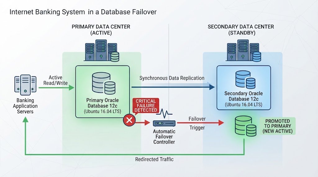
3.2 Database Replication
The existence of a Primary and Secondary Oracle database connected by a replication link is a classic pattern for ensuring data integrity and uptime. This is non-negotiable for financial institutions.
3.3 RESTful API Design
The connections labeled “Makes API calls to [JSON / HTTPS]” indicate a RESTful architecture. The mobile app and the web app communicate with the backend over standard web protocols, making the system platform-agnostic.
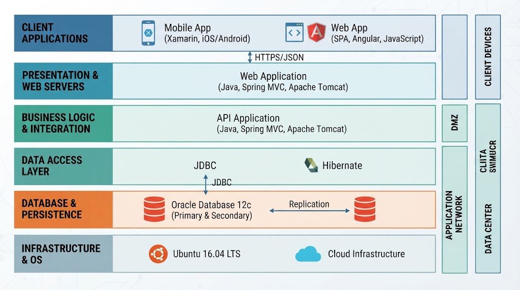
4. The Technology Stack Revealed
For developers and architects, this diagram is a treasure trove of information regarding the specific technologies chosen for this project. The stack includes:
- Mobile: Xamarin (C# based, likely).
- Web Frontend: Angular (JavaScript/TypeScript).
- Backend Framework: Spring MVC (Java).
- Application Server: Apache Tomcat 8.x.
- Database: Oracle Database 12c.
- OS: Ubuntu 16.04 LTS (Server side), iOS/Android/Windows (Client side).
Conclusion
This C4 Deployment Diagram effectively communicates the complexity of the Internet Banking System without getting bogged down in code-level details. It clearly maps out the journey of a user request—from the Mobile App on an iOS device, through the API Application on a Linux server, and finally into the Oracle Database. For anyone learning system architecture, this diagram serves as a perfect example of how to model hardware, software, and their interactions.