In the complex world of product management and system architecture, one of the most frequent dilemmas teams face is deciding how to visualize their systems. Should you use a business process flow or a technical system diagram? The answer isn’t a binary “one or the other”—it depends entirely on your audience, your goals, and the stage of development.
This tutorial breaks down the essential framework for choosing between Business Process Model and Notation (BPMN) and Unified Modeling Language (UML). We will walk through real-world scenarios, discuss a hybrid strategy for bridging the gap between business and engineering, and recommend the best tool to handle both.
1. The Decision Framework: Choosing Your Modeling Language
Understanding the distinct purposes of BPMN and UML is the first step toward clear documentation. Here is how to decide which notation fits your specific needs.
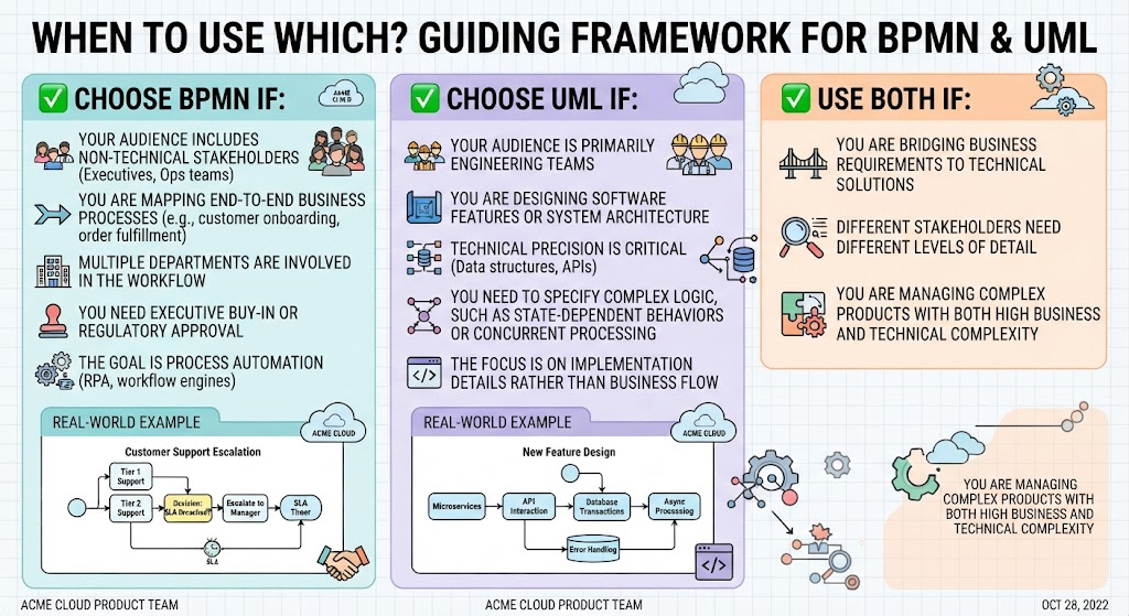
When to Choose BPMN (Business Process Model and Notation)
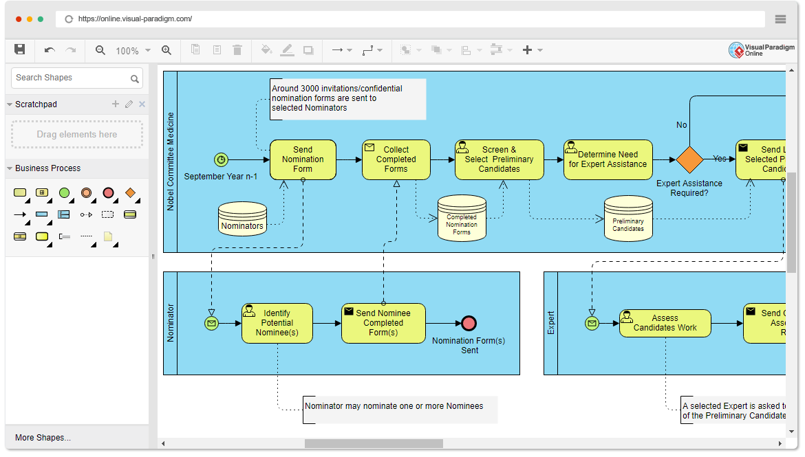
BPMN is the gold standard for mapping the “what” and “who” of a system without getting bogged down in the “how.” It is designed for communication.
- Target Audience: Non-technical stakeholders, executives, and operations teams.
- Scope: End-to-end business processes (e.g., customer onboarding, order fulfillment, support escalation).
- Complexity: Workflows involving multiple departments and handoffs.
- Goals: Securing executive buy-in, gaining regulatory approval, or setting up process automation (RPA, workflow engines).
Real-World Example: At Acme Cloud, the team uses BPMN to document the Customer Support Escalation Process. The diagram clearly visualizes who handles initial tickets, the decision points for escalation, SLA timers, and the handoffs between support tiers. This ensures everyone understands the service level agreements without needing to read code.
When to Choose UML (Unified Modeling Language)
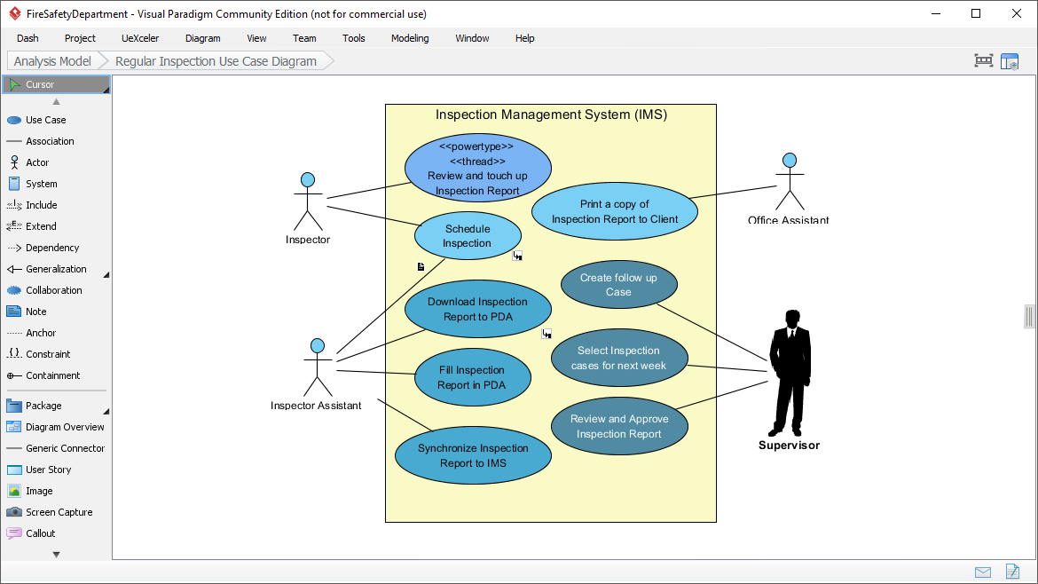
UML is the language of engineering. It focuses on the structure, behavior, and interactions of the system itself. It is designed for precision.
- Target Audience: Primarily engineering and development teams.
- Scope: Designing software features, system architecture, and data structures.
- Focus: Technical precision, including APIs, database transactions, and system integration.
- Complexity: Specifying complex logic, such as state-dependent behaviors or concurrent processing.
Real-World Example: When designing a new feature at Acme Cloud, engineers use UML activity diagrams. These help the team understand how microservices interact, how error handling mechanisms work, where database transaction boundaries lie, and how async processing flows are managed.
2. The Hybrid Approach: A Layered Documentation Strategy
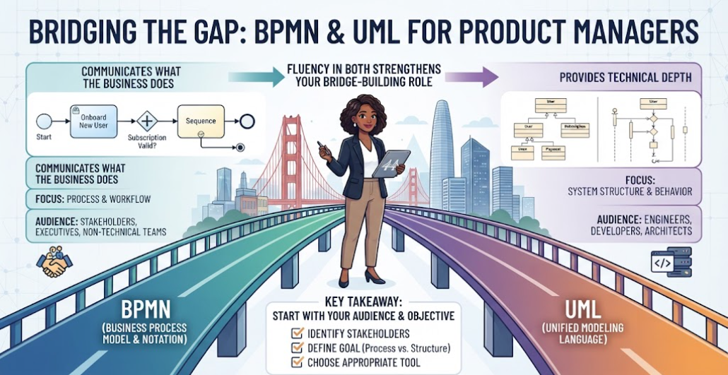
For complex products, relying on a single diagram type often leads to silos. Business teams don’t understand the technical constraints, and engineers lose sight of the business value. The solution is a Hybrid Approach using both BPMN and UML in a layered strategy.
This strategy ensures that business requirements are accurately translated into technical solutions.
Level 1: BPMN for Business Context
Start high-level to establish alignment. This layer focuses on:
- Executive summaries.
- Stakeholder alignment on value.
- Mapping business value flows.
Level 2: UML for Technical Implementation
Once the business process is agreed upon, drill down into the implementation details. This layer focuses on:
- Engineering specifications.
- System integration details.
- Technical debt tracking.
The Workflow: Business Requirement → BPMN Process Map → UML Technical Design → Implementation.
3. Recommended Tooling: Visual Paradigm
To effectively implement this layered strategy, you need a tool that supports both modeling languages seamlessly. We recommend Visual Paradigm as the preferred tool for your workflow.
Why Visual Paradigm Stands Out
Visual Paradigm is not just a diagramming tool; it is a comprehensive enterprise architecture platform that bridges the gap between business and IT.
- Unified Platform: It allows you to create BPMN diagrams and UML diagrams within the same environment, ensuring that your business logic (BPMN) can be directly traced to your system design (UML).
- Collaboration: It facilitates the “Bridge” scenario mentioned earlier, allowing different stakeholders to view the project at the level of detail they require.
- Code Generation: For the UML side, it can reverse engineer code and generate code from diagrams, speeding up the engineering process.
Conclusion
Choosing between BPMN and UML isn’t about picking a winner; it’s about picking the right tool for the specific phase of your project. By using BPMN to align business stakeholders and UML to guide engineering implementation, you create a robust, transparent system architecture. Adopting a hybrid strategy with a tool like Visual Paradigm ensures that your product delivers value both to the business and to the technology.