Building a robust software system begins with a solid blueprint. In the realm of Object-Oriented Design, the Class Diagram serves as this architectural foundation. Whether you are designing a simple inventory tracker or a complex University Information System, mastering how to translate real-world requirements into structured code is a critical skill.
In this tutorial, we will deconstruct a comprehensive example of a University Information System. We will walk through the identification of classes, the definition of attributes, and the mapping of complex relationships like composition and generalization. By the end, you will understand not just how to draw these diagrams, but how to think like a system architect.
Step 1: Identifying the Building Blocks (Classes)
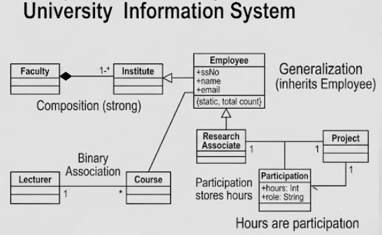
The first step in modeling any system is analyzing the requirements to find the “nouns.” These nouns typically represent the Classes or objects that will exist in your system. In our University scenario, a quick scan of the requirements reveals several key entities:
- Faculty: The administrative body.
- Institute: Academic departments within a faculty.
- Employee: The broad category for all staff.
- Research Associate: A specific type of staff member.
- Course: The academic units being taught.
- Project: Research initiatives.
Tip for Aspiring Modelers: When analyzing requirements, focus on Nouns to find potential classes and Verbs to find operations or relationships. For example, a “Lecturer” (noun) “teaches” a “Course” (verb/relationship).
Step 2: Defining Attributes and Operations
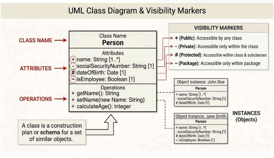
Once you have identified your classes, you must define what data they hold. These are the Attributes. Following standard naming conventions, attributes should be written as singular nouns starting with a lowercase letter (e.g., ssNo, name).
Let’s look at the Employee class:
ssNo(Social Security Number): A unique identifier.name: The full name of the employee.email: Contact information.
Advanced Concept: Static Attributes
Not all attributes belong to a single object. Some belong to the class itself. In our diagram, the Employee class includes a static attribute called counter. This variable tracks the total number of employees across the entire system, rather than just one specific person.
Step 3: Mapping Relationships
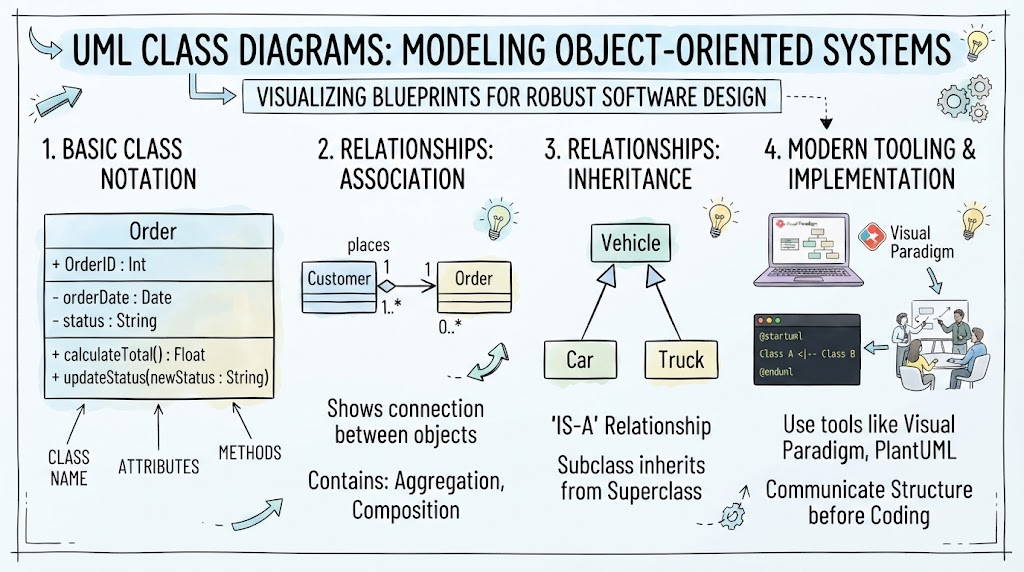
A class diagram is more than just a list of objects; it is a map of how those objects interact. Here are the four critical relationship types demonstrated in the University example:
1. Generalization (Inheritance)
This relationship represents an “Is-A” hierarchy. In the diagram, we see a line connecting Research Associate to Employee. This indicates that a Research Associate is a type of Employee. They inherit all the attributes of an Employee (like name and email) but can also have their own specific properties.
2. Composition (Strong Ownership)
Composition represents a “Whole-Part” relationship where the part cannot exist without the whole. Look at the connection between Faculty and Institute. The filled diamond symbol indicates a strong composition. If a Faculty is dissolved, its Institutes cease to exist. This is distinct from a simple association; it implies strict lifecycle dependency.
3. Binary Association
This is a simple link between two classes. The diagram links Lecturer to Course. This implies that a Lecturer teaches Courses. The numbers (multiplicity) at the ends of the line are crucial:
- 1 next to Lecturer: One specific course is taught by exactly one lecturer.
- * next to Course: One lecturer can teach many courses.
4. Association Class
Sometimes, a relationship has its own data. In this system, the relationship between Research Associate and Project is modeled using an Association Class named Participation. This is a clever way to store attributes that belong to the relationship itself—in this case, the hours a Research Associate spends on a specific Project.
Step 4: Best Practices for Effective Modeling
To create diagrams that are useful to developers and stakeholders, keep these professional tips in mind:
- Practice Abstraction: Do not include every single detail in your first diagram. Focus on the specific development phase you are currently working on to avoid an “unnecessary flood of information.”
- Naming Conventions: Always use Uppercase CamelCase for Class names (e.g.,
UniversitySystem) and lowercase for attributes (e.g.,systemName). - Derived Attributes: If an attribute can be calculated from others (like age derived from a date of birth), mark it with a forward slash (e.g.,
/age) to indicate it is derived.
Conclusion
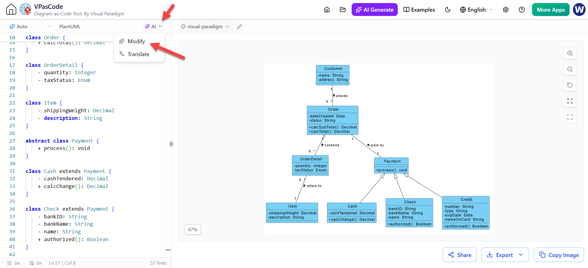
The Class Diagram is an indispensable tool in the software engineering lifecycle. By rigorously defining classes, attributes, and relationships, you bridge the gap between high-level requirements and executable code. Whether you are using Visual Paradigm, UML tools, or AI-assisted coding environments like VPasCode, a well-structured class diagram ensures your system is scalable, consistent, and error-free.