In the complex world of software development, clarity is currency. Before a single line of code is committed to a repository, the architecture of a system must be understood by everyone involved—from the developers writing the logic to the stakeholders defining the requirements. This is where Unified Modeling Language (UML) steps in, specifically the Class Diagram.
Class diagrams are the backbone of Object-Oriented Design (OOD). They serve as the visual blueprints for our software, defining the static structure of the system. By mastering these diagrams, you move from guessing how components interact to knowing exactly how they are built.
1. The Anatomy of a Class: Basic Notation
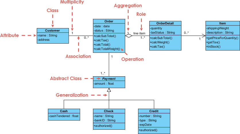
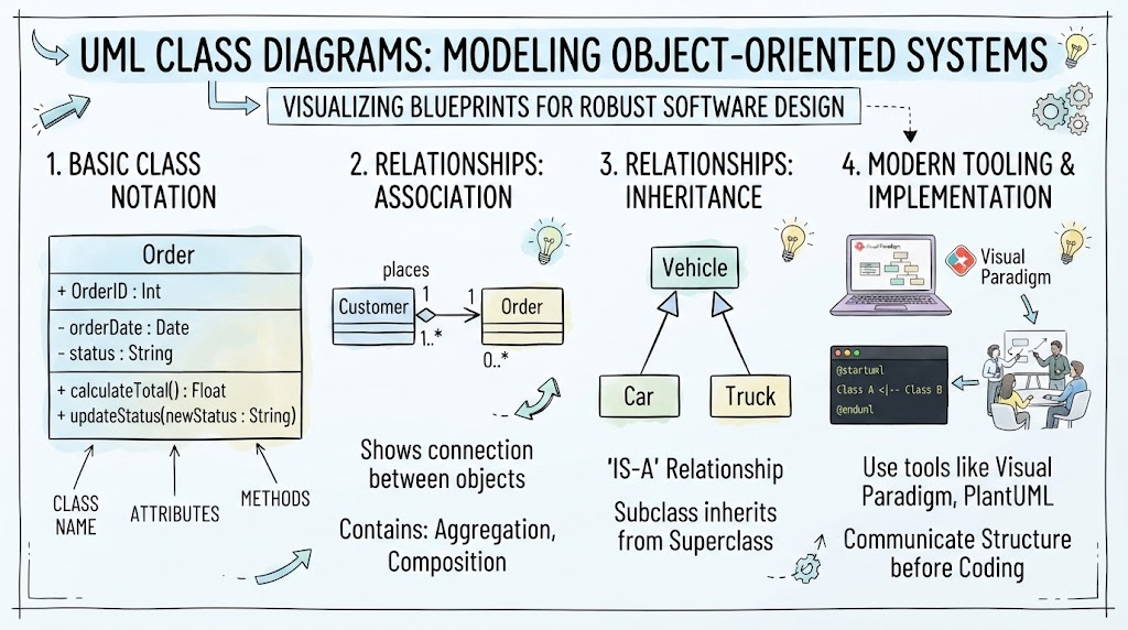
At the heart of every UML class diagram is the Class itself. Think of a class as a factory or a blueprint. It defines what an object looks like and what it can do, but it doesn’t “do” anything until an object is instantiated from it. Visually, a class is represented by a rectangle divided into three distinct compartments.
- The Top Compartment (Class Name): This identifies the entity, such as
OrderorCustomer. Names are typically capitalized and bolded. - The Middle Compartment (Attributes): These are the properties or data members of the class. They define the state of the object.
+ OrderID : Int: A public attribute (indicated by the+) storing an integer.- orderDate : Date: A private attribute (indicated by the-) storing a date.
- The Bottom Compartment (Methods): These are the behaviors or functions the class can perform.
+ calculateTotal() : Float: A public method that returns a floating-point number.+ updateStatus(newStatus : String): A public method that accepts a string argument.
2. Connecting the System: Relationships
Classes rarely exist in isolation. They interact with one another to fulfill business logic. UML uses specific lines and symbols to define these relationships.
Association: The “Placing” Connection
An association represents a structural relationship between two classes. It indicates that objects of one class are connected to objects of another.
Consider the relationship between a Customer and an Order. A customer “places” an order. In the diagram, this is depicted by a solid line connecting the two classes. We often label the line (e.g., “places”) to describe the nature of the connection.
Cardinality is key here:
- 1 (One): A specific customer places exactly one order (in this specific instance).
- 1..* (One to Many): A customer can place one or many orders over time.
Inheritance: The “Is-A” Relationship
One of the most powerful features of Object-Oriented Programming is inheritance. It allows us to create a hierarchy of classes. This is visualized using a solid line with a hollow triangle arrow pointing toward the parent class.
Look at the Vehicle example. Car and Truck are both specific types of Vehicles.
- Superclass (Parent):
Vehiclecontains the general attributes and methods common to all vehicles. - Subclasses (Children):
CarandTruckinherit from Vehicle. They automatically possess the Vehicle’s features but can also have their own unique behaviors.
This “Is-A” relationship ensures code reusability and a logical structure.
3. Modern Tooling: From Whiteboard to Code
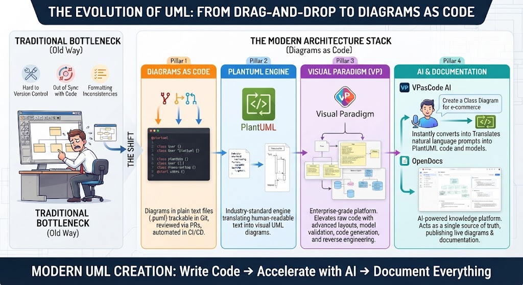
In the past, class diagrams were drawn on whiteboards or paper. Today, we leverage sophisticated tools that bridge the gap between design and implementation.
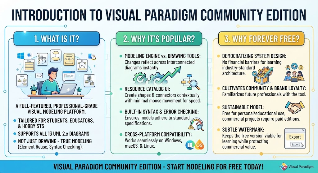
Visual Paradigm
Tools like Visual Paradigm offer a robust graphical user interface (GUI). They provide drag-and-drop functionality to create complex diagrams, manage project metadata, and ensure that the visual representation matches the actual code structure.
PlantUML: Code as a Diagram
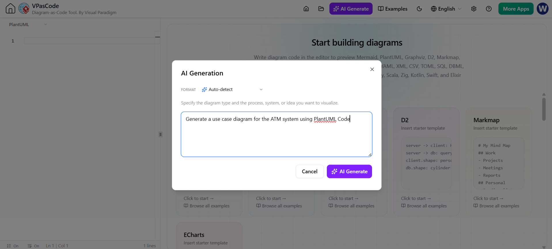
For those who prefer a developer-centric workflow, PlantUML is a game-changer. Instead of drawing boxes, you write code to generate diagrams.
 @startuml
 Class A <|-- Class B
 @enduml
This approach allows you to version-control your architecture alongside your codebase, ensuring that your documentation evolves with your project.
Conclusion
Whether you are sketching a simple Order class or modeling a complex inheritance hierarchy like Vehicle, UML Class Diagrams provide a standardized language for communication. By understanding the notation, relationships, and modern tools available, you can design robust systems that are easier to maintain and scale.