


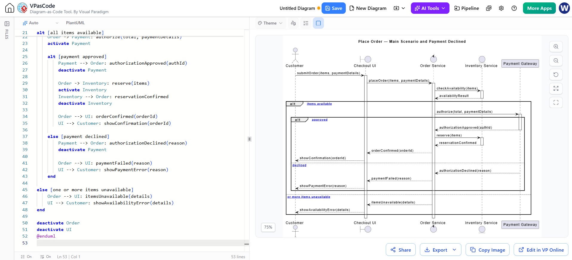
In modern software architecture, the ability to model complex interactions between users, interfaces, and backend services is crucial. The “Place Order” scenario is a classic example of a business process that requires strict sequencing, conditional logic, and external system coordination. This tutorial explores how to construct a robust sequence diagram using PlantUML within the VPasCode environment, focusing on handling the “Happy Path” alongside critical alternative flows like payment declines.
Understanding the System Participants
Before diving into the logic, we must identify the roles involved in the transaction. A sequence diagram visualizes the interaction between these actors over time. In this specific architecture, we utilize four distinct participant types:
- Customer (Actor): The external initiator of the process, representing the human user interacting with the system.
- Checkout UI (Boundary): The interface layer that accepts input from the customer and presents the final status. It acts as the entry point for the business logic.
- Order Service (Control): The central brain of the operation. It orchestrates the flow, validates data, and coordinates the interaction between inventory and payment systems.
- Inventory Service (Entity): A backend service responsible for checking stock levels and reserving items.
- Payment Gateway (External System): An external dependency used to authorize financial transactions.
Modeling the Logic with Alt Fragments
The core complexity of this diagram lies in the decision points. In PlantUML, the alt (alternative) fragment is used to define conditional logic. This allows the diagram to branch out based on the state of the system, effectively modeling both success and failure scenarios.
1. The Availability Check
The first critical decision point is inventory availability. Before any money changes hands, the system must ensure the product exists. This is modeled using a primary alt block:
alt [all items available]
    Order -> Payment: authorize(total, paymentDetails)
    activate Payment
    ...
else [one or more items unavailable]
    Order --> UI: itemsUnavailable(details)
    UI --> Customer: showAvailabilityError(details)
end
Here, if the condition [all items available] is met, the flow proceeds to the payment stage. If not, it immediately routes to the error handling block, returning a message to the UI.
2. The Payment Decision
Once inventory is confirmed, the order is sent to the Payment Gateway. This triggers a nested alt structure to handle the financial outcome:
alt [payment approved]
    Payment --> Order: authorizationApproved(authId)
    deactivate Payment
    Order -> Inventory: reserve(items)
    ...
else [payment declined]
    Payment --> Order: authorizationDeclined(reason)
    deactivate Payment
    Order --> UI: paymentFailed(reason)
    UI --> Customer: showPaymentError(reason)
end
This nesting demonstrates how complex real-world scenarios can be flattened into a readable visual format. The logic clearly distinguishes between the authorization approved path (leading to item reservation) and the authorization declined path (triggering a user-facing error).
Visualizing Object Lifecycles
A vital aspect of sequence diagrams is the activation bar, which indicates when an object is actively processing. In VPasCode, this is handled automatically by the activate and deactivate keywords.
- Activating: When
OrdercallsInventory, theactivate Inventorycommand tells the diagram engine to draw a vertical bar on the Inventory lifeline. This signifies that the Inventory service is busy. - Deactivating: Once
Inventorysends back thereservationConfirmedmessage,deactivate Inventoryis called, ending the bar. This visual cue helps developers understand exactly how long resources are held during a transaction.
From Logic to Visualization
The power of VPasCode lies in its ability to render these text-based definitions into professional diagrams in real-time. By writing the code on the left, the system renders the graphical representation on the right. The diagram automatically aligns the participants, draws the arrows representing message flow, and highlights the decision branches using the alt framing boxes.
This approach ensures that your documentation stays synchronized with your codebase. Whenever the business logic changes—such as adding a new payment method or altering the reservation strategy—you only need to update the source text, and the diagram updates automatically.