


Visualizing High-Level Architecture
Welcome to this tutorial session. Today, we are going to explore the art of high-level system architecture visualization. Specifically, we will be looking at how to define the boundaries of a system and its interactions with the outside world using a System Context Diagram. We will use PlantUML—a powerful diagram-as-code tool available within Visual Paradigm—to bring these concepts to life.
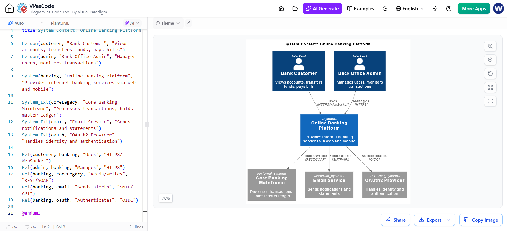
Imagine you are designing an Online Banking Platform. Before diving into complex database schemas or code logic, you need to answer one fundamental question: “What is this system, who uses it, and what does it talk to?” The diagram we are about to build answers exactly that.
Defining the Actors
Every system starts with people or other systems interacting with it. In our scenario, we have two primary human actors:
- The Bank Customer: This is the end-user who wants to view accounts, transfer funds, and pay bills. They are the reason the system exists.
- The Back Office Admin: This is the internal operator responsible for managing users and monitoring transactions. Their role is crucial for maintenance and oversight.
In PlantUML, we define these using the Person keyword. It’s important to remember that these aren’t just labels; they represent the “actors” in your software ecosystem.
The Central Hub
At the heart of our diagram sits the Online Banking Platform. This is the system itself. In the context of C4 modeling (which this diagram style follows), this represents the top level of abstraction. It provides internet banking services via web and mobile interfaces. By placing this centrally, we establish it as the focal point of all activity.
Navigating External Dependencies
No modern banking application lives in isolation. To function, it must connect to several critical external systems. These are often referred to as “External Systems” in architectural terms. Let’s look at the three key dependencies in our example:
- Core Banking Mainframe: The legacy powerhouse. While the online platform is the face, the mainframe holds the master ledger and processes the actual financial transactions. It typically speaks older protocols like SOAP or REST.
- Email Service: A utility required for communication. Whether it’s sending daily statements or transaction alerts, the banking platform needs a way to reach out to customers via SMTP.
- OAuth2 Provider: The gatekeeper. Security is paramount in banking. Instead of building authentication from scratch, the platform relies on an external identity provider using OIDC (OpenID Connect) to verify who is logging in.
Mapping the Connections
Now that we have our components, we need to draw the lines between them. In a System Context Diagram, these lines are not just connectors; they are relationships defined by specific data flows and protocols.
Let’s trace the flow of information:
- User Interaction: When a customer logs in, they communicate over HTTPS/WebSocket. Similarly, the admin manages the system via HTTPS. These secure channels ensure data integrity.
- Data Synchronization: The platform reads from and writes to the Core Banking Mainframe. This bidirectional relationship is vital—when you transfer money, the online app updates the mainframe.
- Communication & Identity: Finally, notice how the platform sends alerts to the Email Service and authenticates against the OAuth2 Provider. These arrows clearly indicate the direction of control and data flow.
By defining these relationships explicitly with their protocols (like REST/SOAP or SMTP/API), you create a blueprint that developers can actually implement. You aren’t just drawing boxes; you are documenting contracts.
Why Use PlantUML?
You might wonder why we use code to draw diagrams instead of drag-and-drop tools. The answer lies in version control and clarity. With PlantUML, your architecture is text-based. This means you can track changes over time, review designs in pull requests, and generate diagrams instantly. As seen in the interface, Visual Paradigm’s VPasCode makes this transition seamless, allowing you to write code on the left and see a professional diagram render on the right.
Key Takeaways
To wrap up this session, let’s recap the essential skills we’ve covered:
- Scope Definition: Learn to identify the main system versus external entities.
- Actor Identification: Clearly distinguish between different types of users (Customer vs. Admin).
- Protocol Awareness: Always label your connections with the technology used (HTTPS, REST, SMTP).
- Documentation as Code: Embrace tools like PlantUML to keep your documentation maintainable and up-to-date.
By mastering these basics, you can effectively communicate complex system architectures to stakeholders, ensuring everyone is on the same page before a single line of code is written.
Related posts:
 Master Conversation-Driven C4 Modeling with AI
 Refining Use Case Diagrams: From Basic to Advanced E-commerce Models
 Mastering the C4 Model: A Step-by-Step Guide to the Container Diagram for an Internet Banking System
 Mastering Software Architecture: A Deep Dive into C4 Component Diagrams with Visual Paradigm