Understanding the Evolution of System Requirements
Welcome to this tutorial on refining system models. When we first start modeling software requirements, it is common to focus on the “happy path”—the ideal scenario where everything goes smoothly. However, real-world systems are rarely that simple. Today, we will walk through a transformation of an E-commerce platform model, moving from a basic representation to one that handles complex business logic.
The Starting Point: A Basic Model
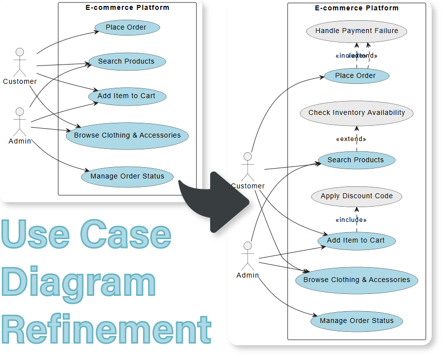
Let’s look at the initial state of our diagram. On the left side, we see a standard structure involving two primary actors: the Customer and the Admin. The Customer interacts with the system to search for products, browse clothing, add items to their cart, and place orders. Meanwhile, the Admin focuses on managing order statuses.
This model serves as a solid foundation. It answers the question, “What can the user do?” But if you were building this application today, would you be satisfied knowing only these features exist? Probably not. You need to know what happens when things go wrong or when specific conditions must be met.
Diving Deeper: Introducing Specialized Logic
To make our system robust, we need to refine the interactions. Let’s take the core action of Place Order. In the advanced model on the right, we realize that placing an order isn’t just a single step; it relies on other processes.
- Handling Failures: What happens if a customer tries to pay but the transaction fails? We introduce a new specialized use case called Handle Payment Failure. Notice the arrow pointing from this new function back to the main Place Order action. This indicates that if a failure occurs, the system triggers this specific handling routine.
- Checking Inventory: Before an order can be finalized, the system must ensure stock exists. We add a Check Inventory Availability use case. This ensures the business logic remains accurate before committing to a sale.
Mechanisms of Refinement: Include vs. Extend
In Visual Paradigm, we have powerful tools to represent these relationships clearly. As we refine the diagram, we utilize two key stereotypes: <<include>> and <<extend>>.
The Power of <<include>>
An include relationship represents mandatory behavior. If you look at the Add Item to Cart use case, you’ll see it includes the Apply Discount Code functionality. Why include it? Because every time a user adds an item, they might want to apply a code. Even if they don’t actually enter one, the option (or the check) is part of the standard flow. It is an essential component of the larger process.
The Flexibility of <<extend>>
On the other hand, an extend relationship represents optional behavior triggered under specific conditions. Look at the connection between Place Order and Check Inventory Availability. Here, checking inventory extends the ordering process. This means the base process is valid on its own, but in certain scenarios—like high-demand sales—the inventory check becomes necessary. This distinction allows us to model complexity without cluttering the main user journey.
The Result: A Robust Architecture
By the end of this refinement, our diagram tells a much richer story. We still maintain the core interactions for the Customer and Admin, ensuring the user experience remains intuitive. However, underneath the surface, we now have a detailed map of error handling, inventory management, and promotional logic.
Key Takeaways
As we wrap up this session, remember that a good use case diagram is iterative. Start with the basics, then peel back the layers to reveal the hidden complexities of your system. By using mechanisms like Include and Extend, you can create diagrams that are not just visually appealing but technically precise, ready to guide your development team effectively.